In part 1 of this build and review article I have been looking at the general features of the Quadlugs multirotor modular system and some preparation steps required before the actual frame assembly, namely the drilling of holes in some of the lugs.
2. Quadlugs quadcopter frame assembly
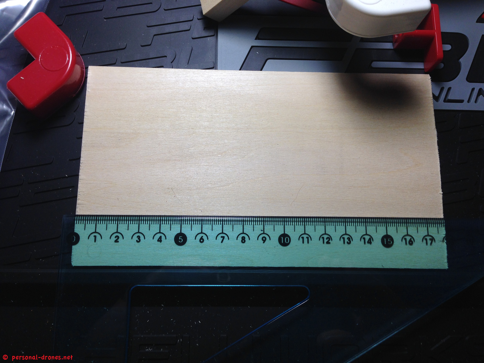
Before we actually assemble the frame, we have adapt the bottom plate, which is slightly larger than possibly needed.
The original size of the provided bottom plate is 17,9 x 10,1 cm (and 3 mm thick):
The plate could actually fit in the frame as it is, so why do we have to trim it down?
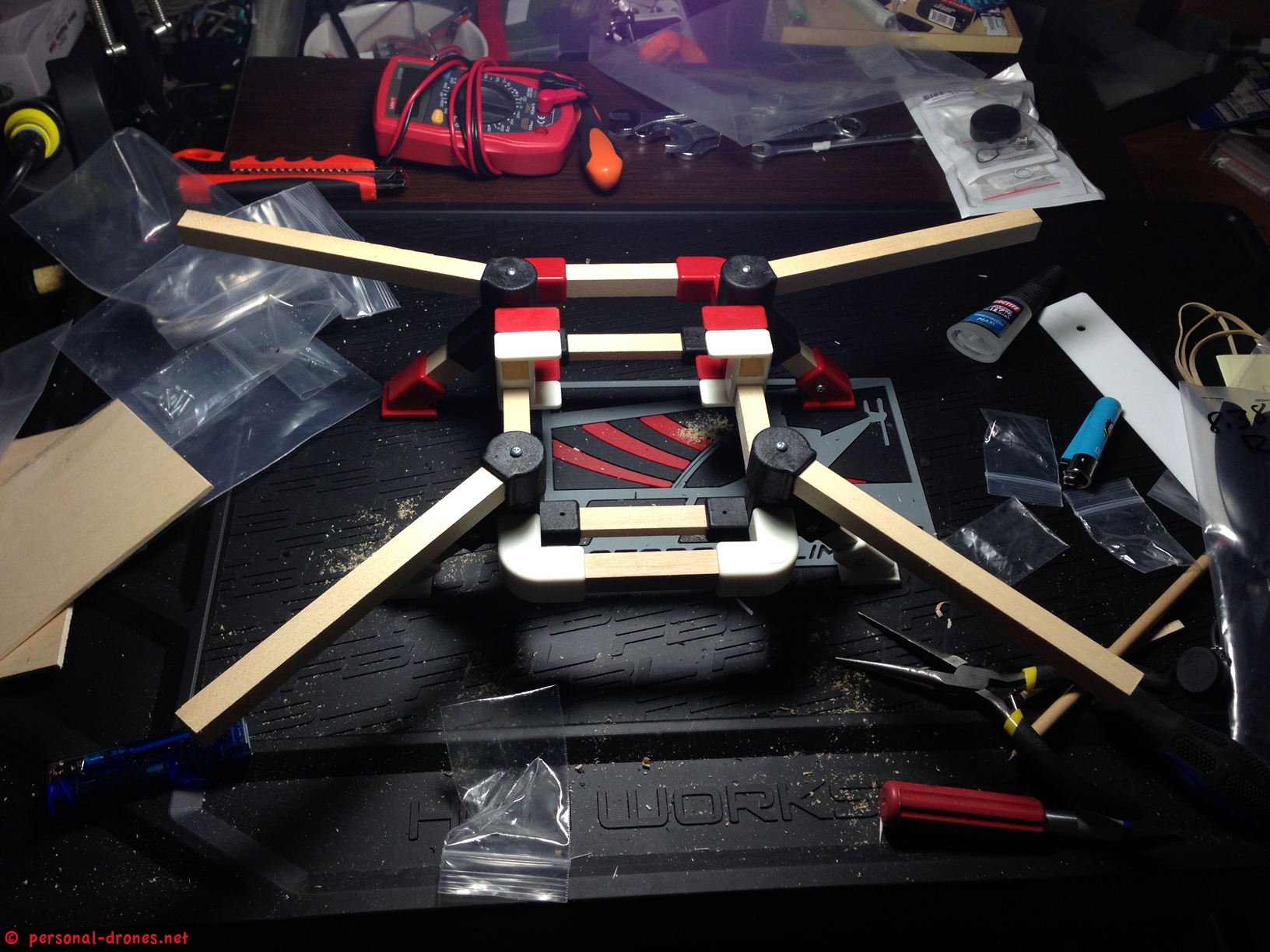
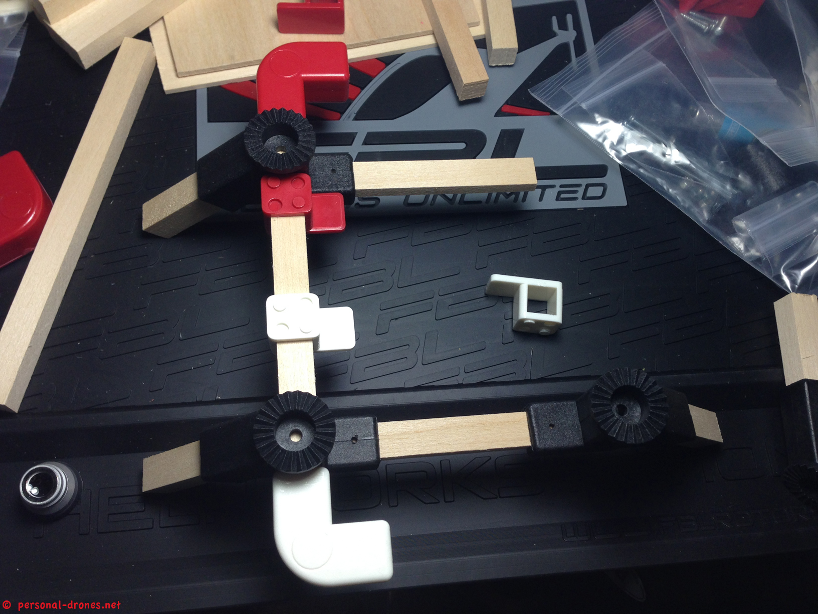
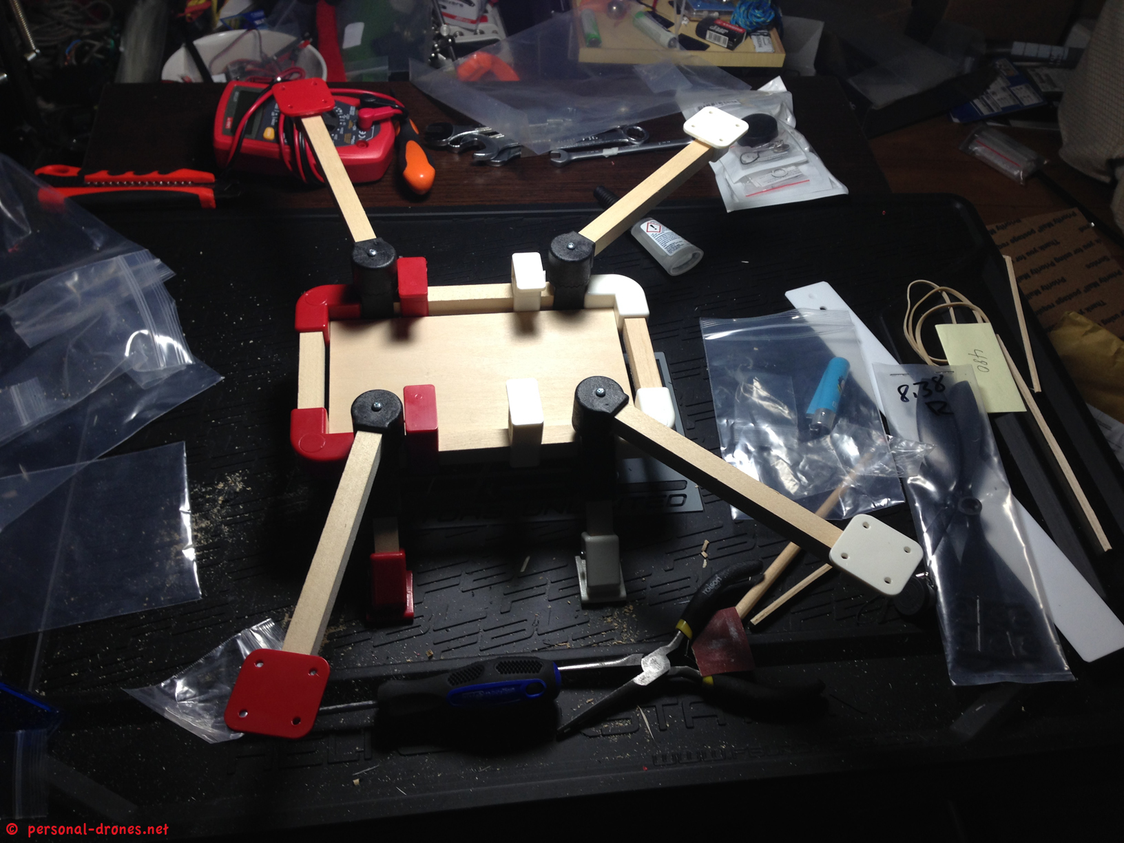
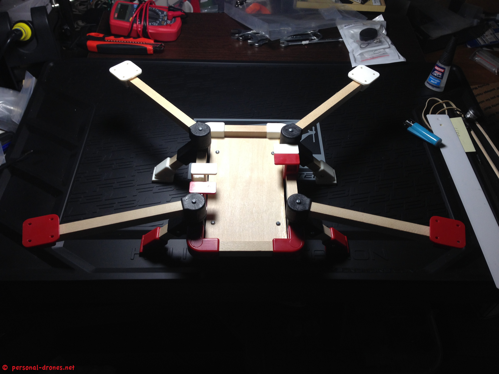
The answer is in the photo below, where the partially assembled “scaffold” of the frame is shown. When the four “perimeter” wood pieces are put in place, hold by the angle lugs, and the two transversal reinforcement bottom pieces are fitted in their hole in the arm lugs, and everything is strongly pressed together both in vertical and horizontal directions, to get all the wood pieces reach the end of their respective holding holes in the lugs, then the bottom plate as it is, will not fit anymore.
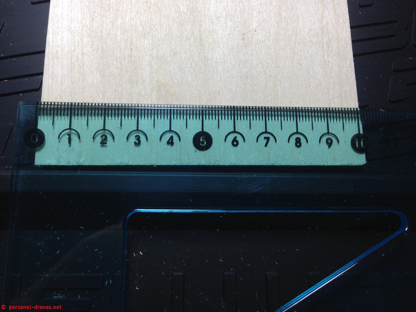
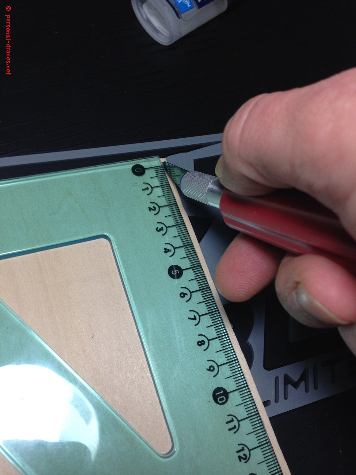
I actually found I had to cut down the deck to 17,5 x 9,8 cm in order to fit the “compacted” frame scaffold.
Once we have cut the lower deck to the correct size we are ready to assemble the frame. At this time it is wise to assemble everything but the upper deck. Since the upper deck will make the area of the bottom plate under it hardly reachable, we will only mount it after all electronics and FPV equipment is mounted on the lower deck.
The frame assembly. First the “scaffold” is put together, as shown in the next picture. At this stage we leave the upper parts of the arm lugs and the arms aside and concentrate on the lower part of the frame:
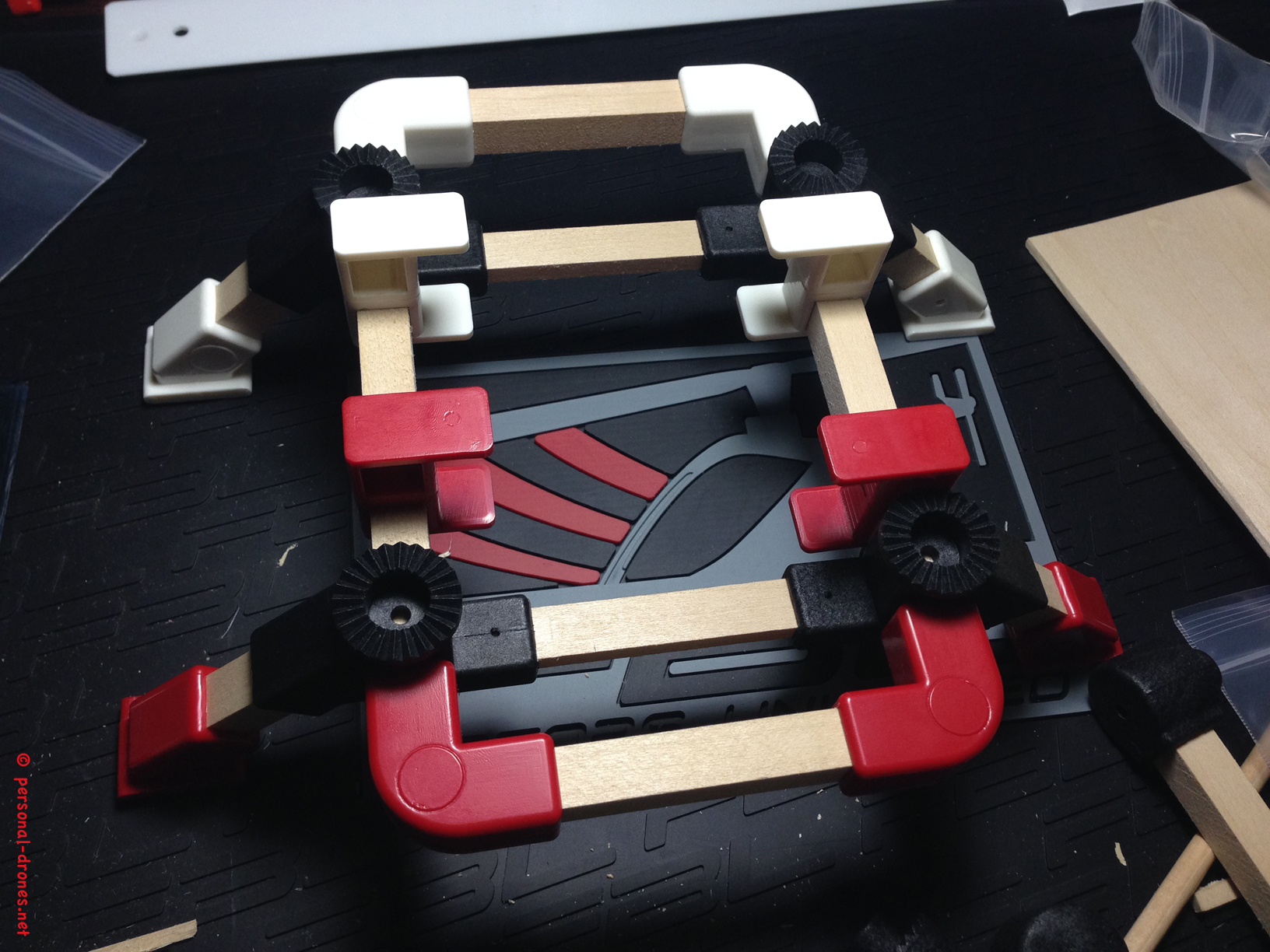
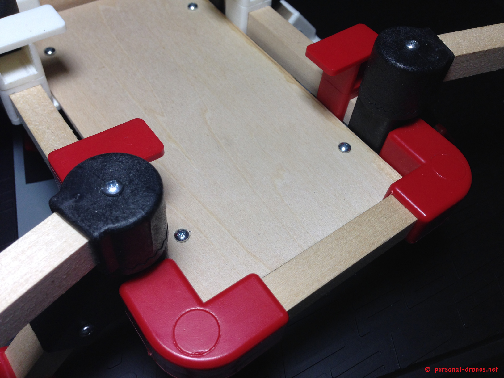
Once you have the lower part of the frame assembled as shown above, you can start putting the first screws in. As you see in the picture above, the angle lugs were placed so that the screw heads will be located at the bottom of the quad. See how you do not see the screw holes from above, in the picture. So while assembling the frame mind the orientation of the angle lugs (actually of all lugs).
I suggest you start by putting in the 8 screws for the 4 angle lugs, as a first consolidation step. Keep the frame tightly pressed together while you screw, you want a perfect job here.
Next, time to fix the arm lugs, with upper pieces, arms and legs, to the frame. To this end, insert the arms into the arm lugs. Again make sure you press the wood pieces to the very end of their holes on the lugs each time.
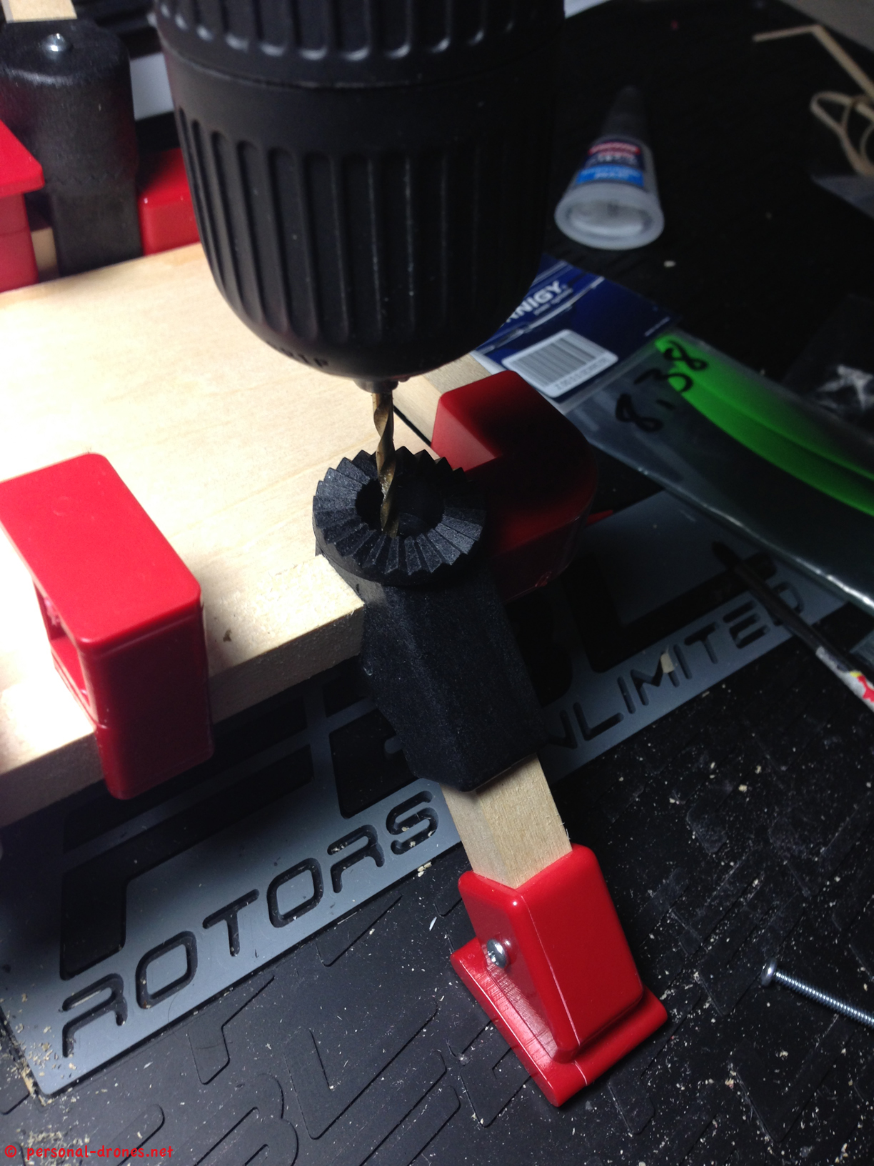
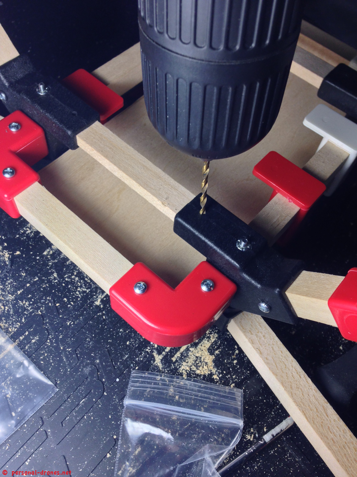
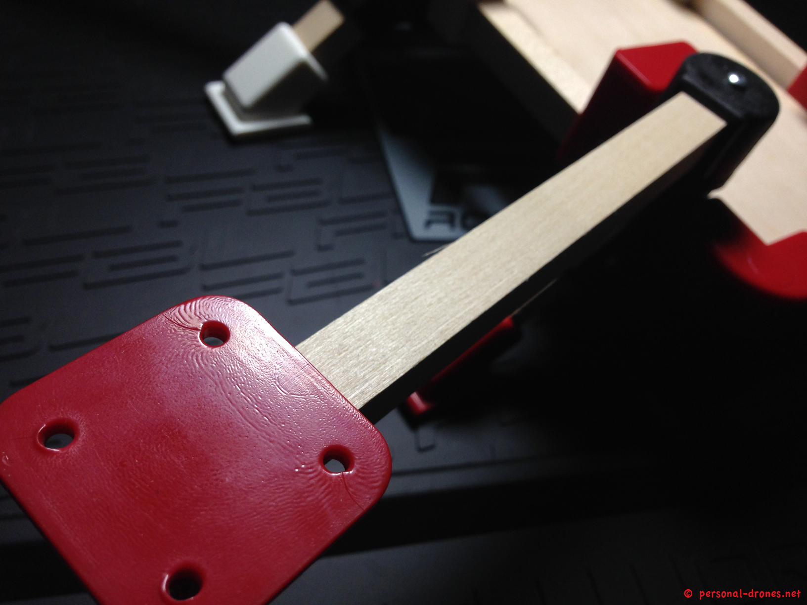
To fix the arm lugs to the frame you will have to drill, with the 3 mm bit, through 2 pieces of wood: the arm, on top, and the frame perimeter piece, on bottom. I have first drilled the bottom part, as shown in next picture, and then the top part with the arm. Make sure you keep the arm lug tightly pressed to the respective angle lug while drilling.
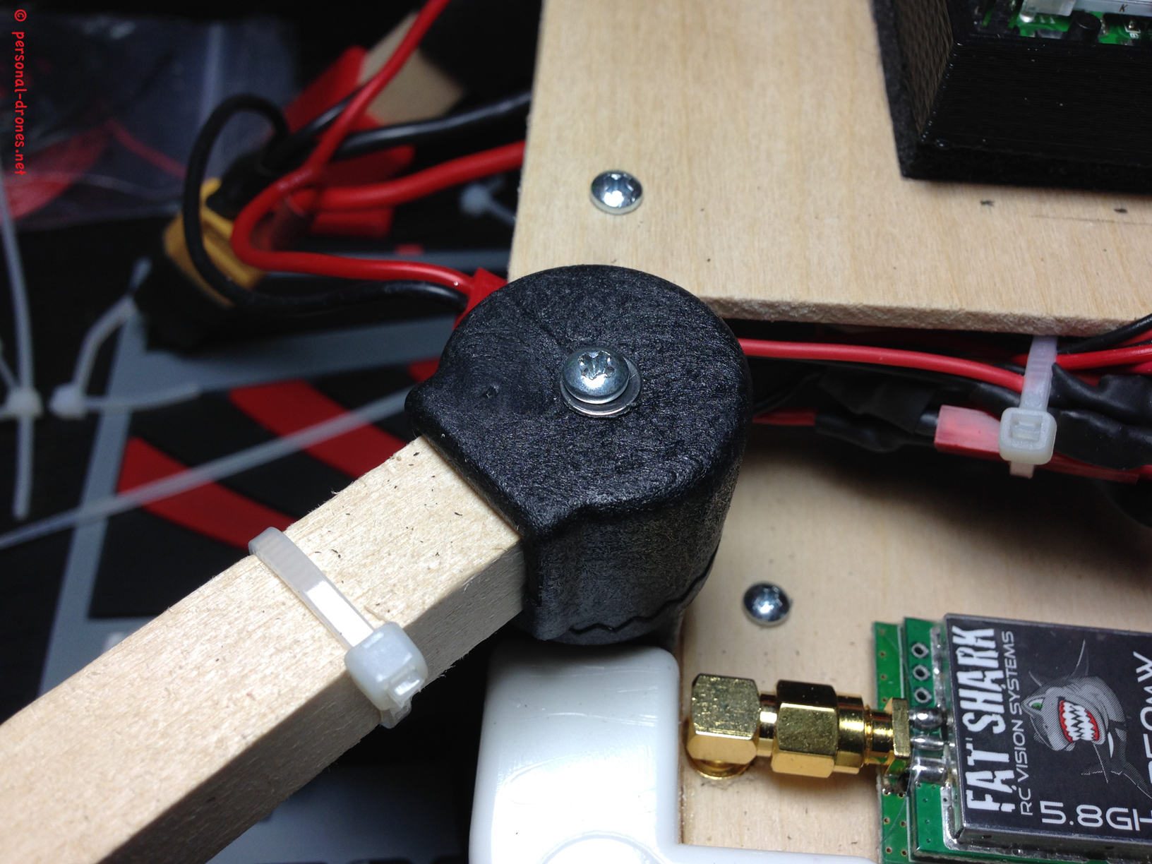
Then I positioned the top part of the lug, with the arm inserted, on top of the bottom part, and drilled thought the arm. So now we have a hole that goes through the length of the whole arm lug where we can insert the provided long screws, fixed by the bottom nut in place. This will tighten the arm to the lug, and the lug to the frame. I found out this will be a very strong lock as the quality and strength of the arm lugs is really excellent, this is no cheap loose plastic, but sturdy nylon. Quadlugs did a great job here and these arm lugs are really the key of the system, as already discussed in part 1 of this review.
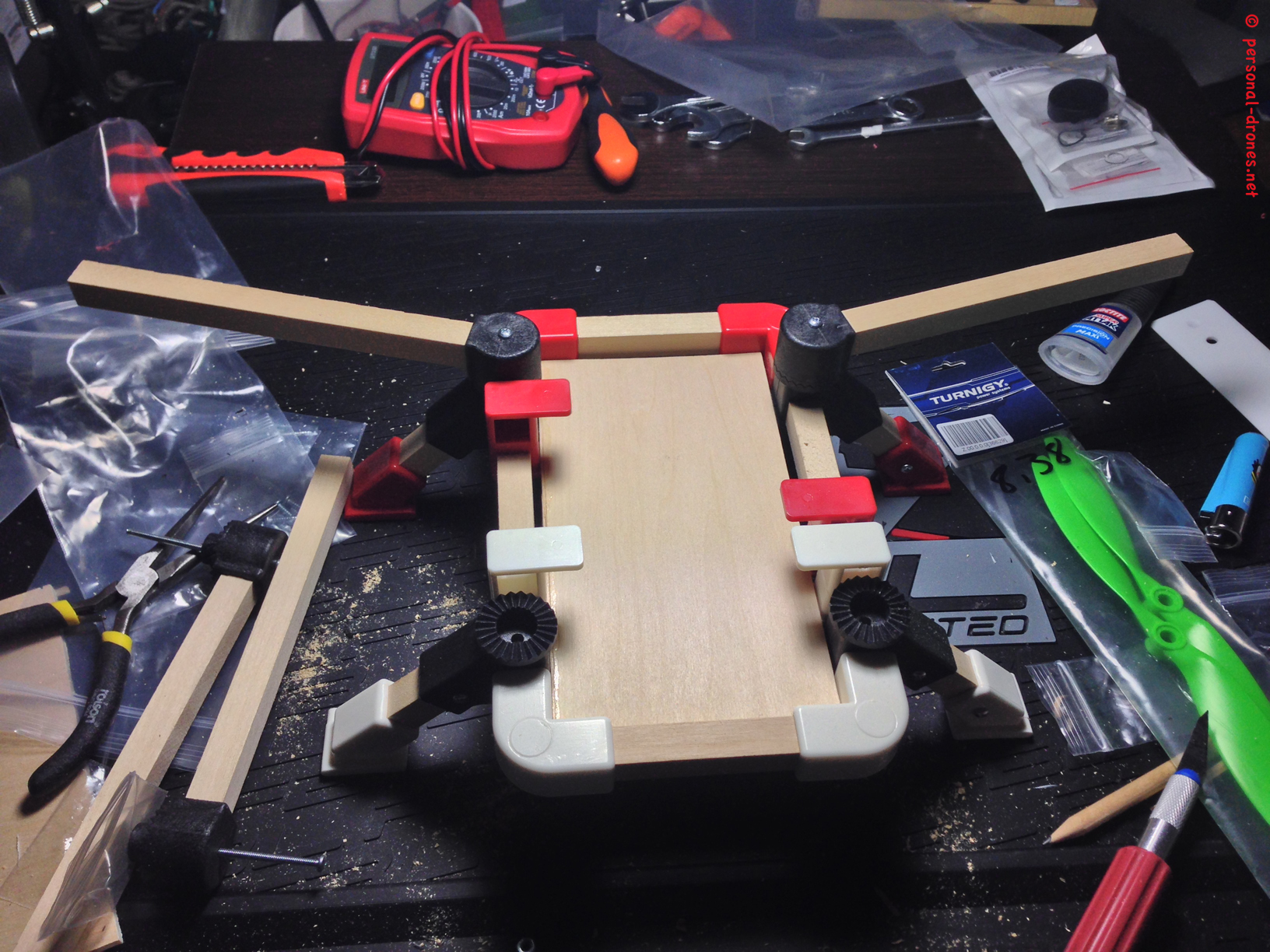
The picture above shows the 4 arms in place. Mind that later on 4 M3 washers were added under the head on the long arm lugs screws, to allow for a tighter fit. Although the nylon is very strong, in the long rung washers might help to prevent wear of the material.
Let’s repeat once more that the the top part of the arm lugs, the one that holds the arm itself, can be rotated in 15 degrees increments with respect to the bottom part. You can easily change this at any time, even in the field, by just loosening a bit the long screw, rotating the arm to your desired position, and then tightening the screw again. This is a quite amazing and unique feature I am very happy with.
In the picture above, see how I decided to keep the front arms at a wide angle, in order to stay clear from the field of view of the wide angle camera. You can also mount them at 90 degrees with respect to the frame, as in an H quad. Love this feature.
OK time to fix the lower deck to the structure. In order to do this we take advantage of our hole number 2 that we drilled at the start of the build. It’s actually the very same drill, except that this time we have the wood of the reinforcing transversal wood piece in between the two holes, and the drill will be extended to the deck, that we have to keep firmly in place during the drilling.
Once the holes are drilled, we can screw the plate to the frame.
We can now mount the motor plates and screw them to the arms by using hole 4 we drilled in part one of this review.
And we are done with frame assembly, here is the final result:
A final note on the landing lugs and legs: get the landing surface flat. It you see that the quad tend to wobble, carefully check out the length of the legs. I had one that was slightly longer than the others, took a while to realize that. When I adjusted the length of the leg (this was just a 2 mm cut), then the quad finally stayed perfectly flat. So make sure you check this our while adjusting the landing gear. Also, the provided default landing legs are slightly shorter than what I would love to have, so I will probably build some longer ones soon.
In the next part of the review, we will see how to mount the electronics on this frame, to have it in the air. I want to anticipate that the first flight tests show that the machine flies great and stable, it’s really looking like an excellent platform for aerial video and FPV.
Please stay tuned on the blog for the follow up of this article. In the meanwhile make sure you check out the Quadlugs web site and the Quadlugs build videos, that are very rich in details and provide step by step build instructions for the Quadlug system.
Quadlugs modular multirotor system review
3 thoughts on “QUADLUGS MODULAR MULTIROTOR SYSTEM QUADCOPTER BUILD AND REVIEW – PART 2”