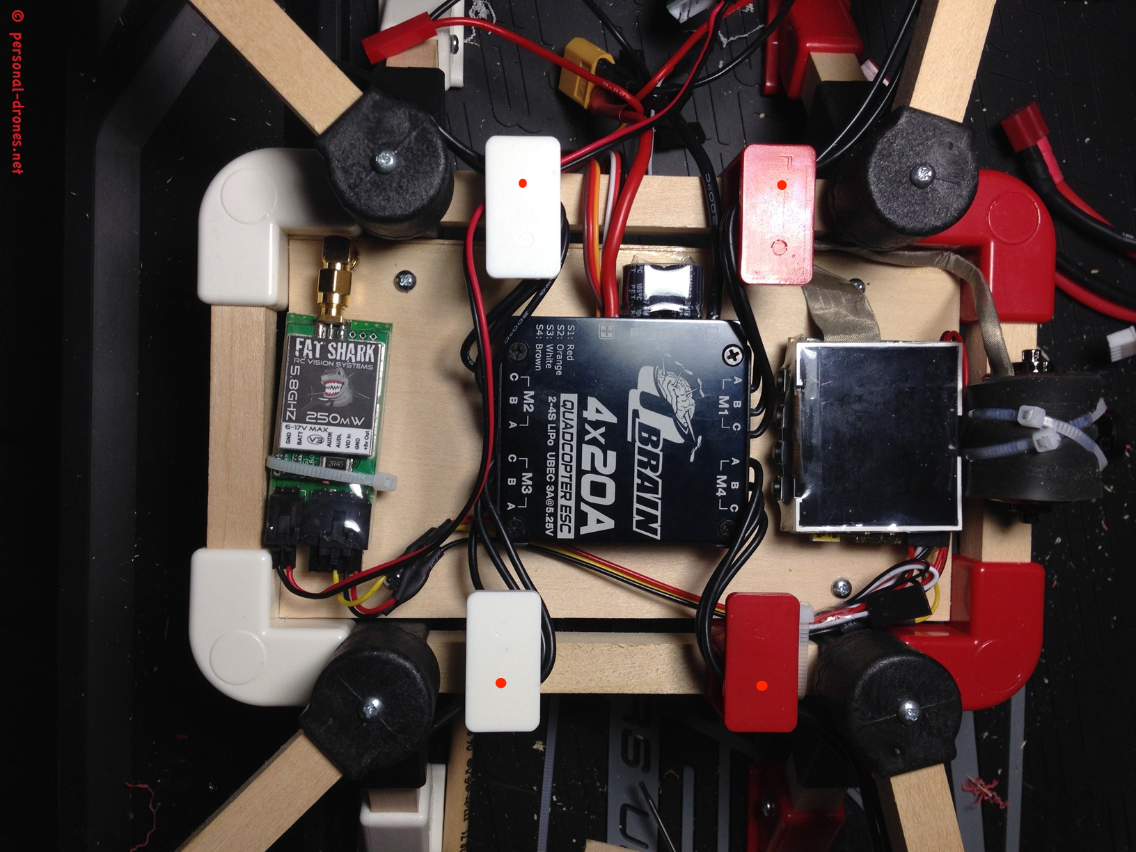
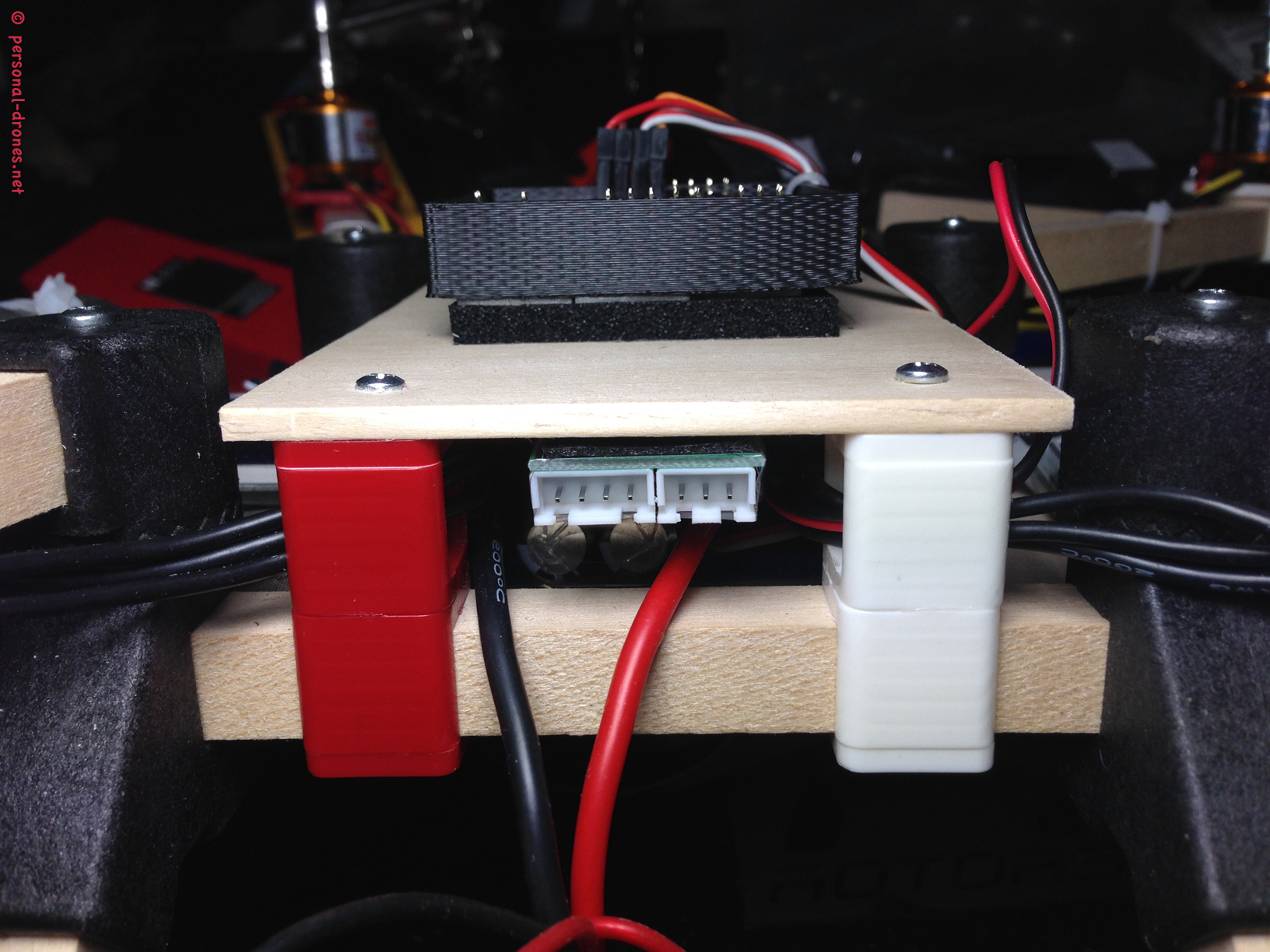
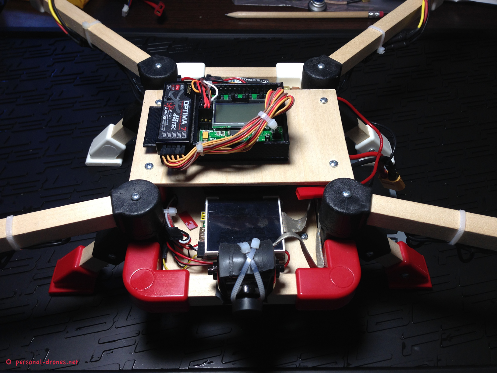
If you followed up to here in this multi part article on the Quadlugs multirotor building system, you know that we are now at a stage in which we have a basically fully assembled 480 mm quadcopter, with motors, escs, and FPV equipment in place. In the image below the placement of the electronics on the lower board is shown. We will have to drill the 4 positions marked by red spots in the figure in order to secure the upper deck in place.
We now need to finish the build by mounting the upper deck with control board and radio receiver. mounting the upper deck is straightforward. First, drill the upper plate lugs in the positions marked in the figure above. You should do this with extreme care as the ESC wires, in the suggested configuration, run into the lug hole. You could also remove the wires while you do this, or drill before inserting the wires. Then with a pencil, carefully mark the position that correspond the the drilled holes to the wood board. Mind that the board, like the lower board, is larger than required. I did cut down mine to 8.5 x 13.5 cm in order to fit this design.
For screwing, I recommend the short screws supplied with the Quadlugs kit. They are perfect for this and are just long (short) enough to span the board height and the plastic of the lug, protruding only minimally on the hole below so that the tips of the screws will not interfere with any electronics below.
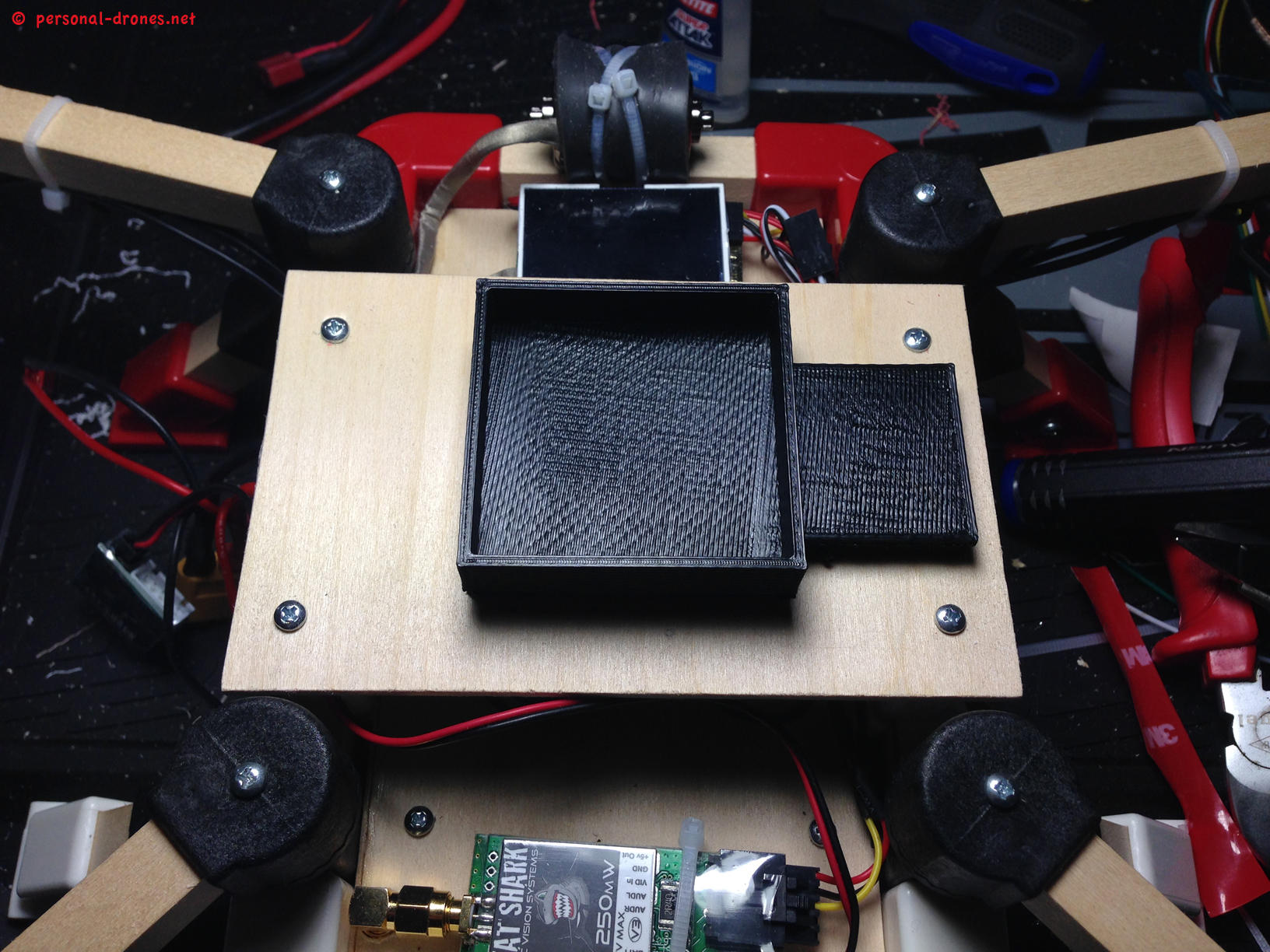
And here is the nice KK2 board enclosure provided by Quadlugs. It is a brilliant and simple design, an absolutely perfect fit to the KK2 board that once inserted in, will not come out easily. Quadlugs recommend to put some hot glue on the corners, but I feel this is not strictly required.
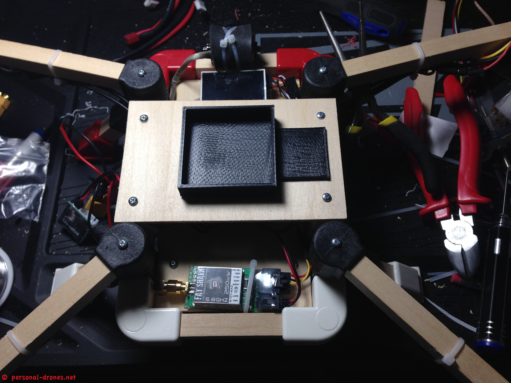
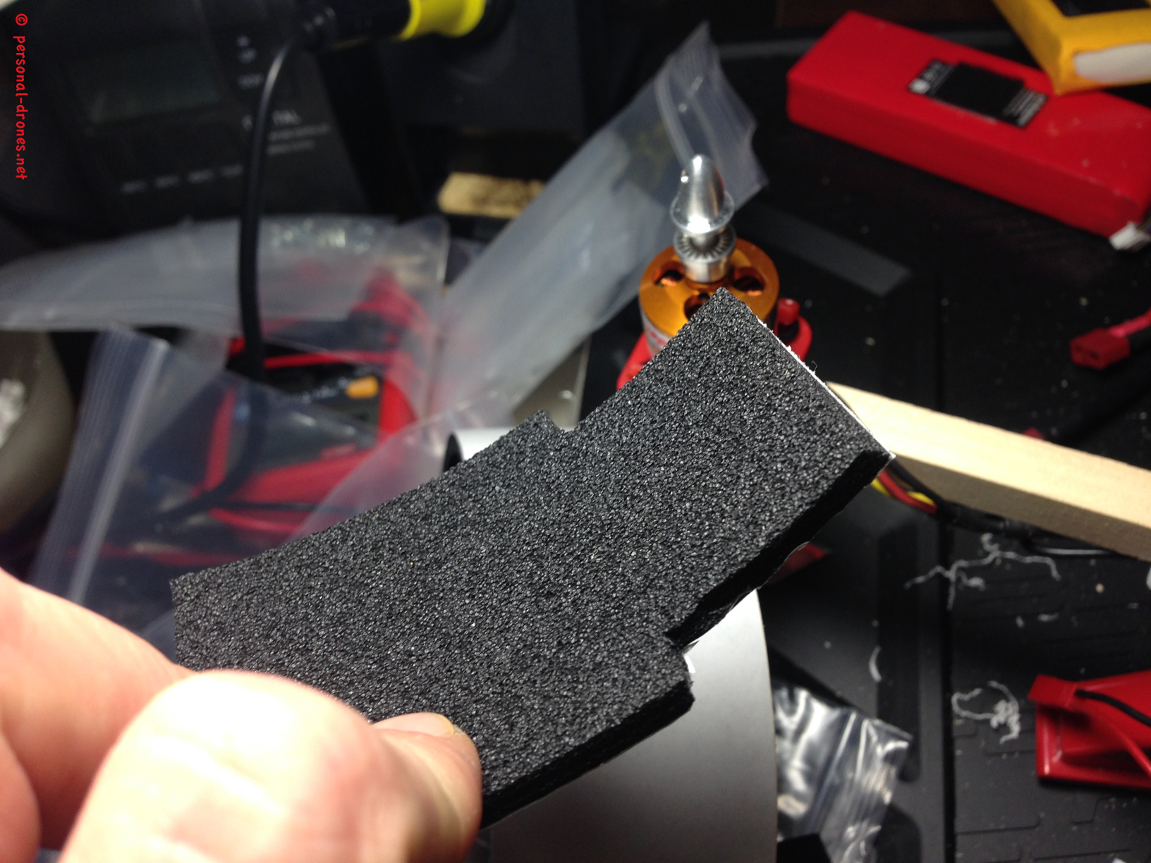
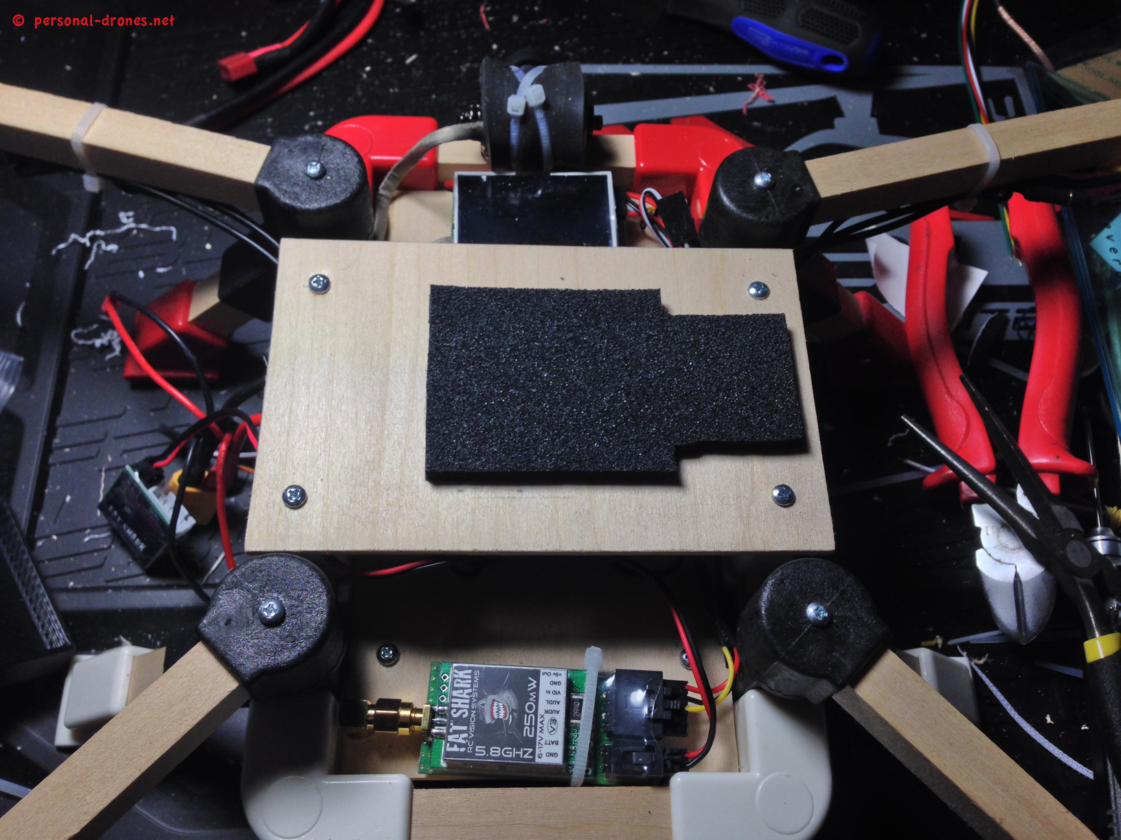
The position of the board was carefully calculated in oder to have the board dead center. I did cut out a piece of vibration absorbing foam with the shape of the enclosure:
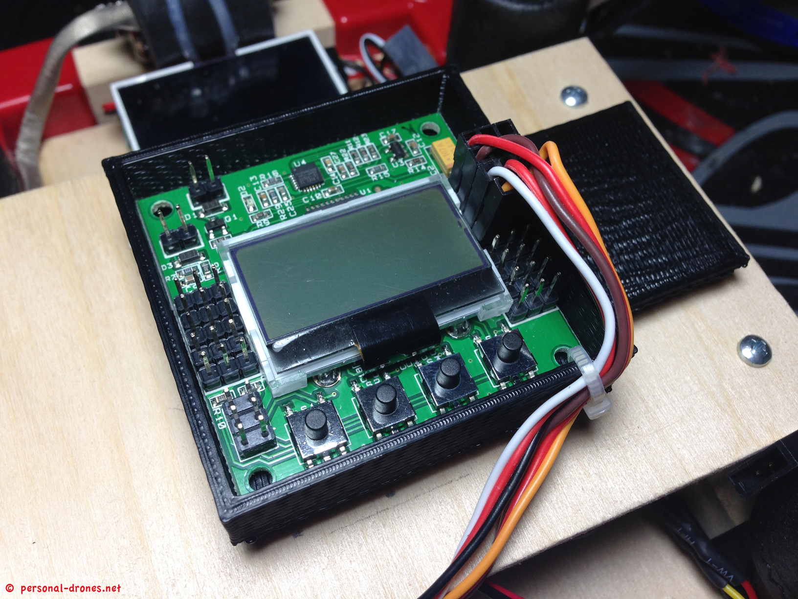
The picture above shows the ESC signal wires from the ESC block inserted into the board, in the ESC pins. This is the column of pins in the right side of the board. Mind color and order. For our configuration, described in part 3 of this article:
- Signal wire M1 (red) goes in the upper row of 3 pins. The signal wires alway go to the inside of the board, as in the picture.
- Signal wire M4 (brown) goes to the second rows of pins, as in figure
- Signal wire 3 (white) goes to the third row. This connector also carries the red and black power wires while the others only have the signal wire. In this configuration we will have to move the 2 power black and red wires to the connector with the signal wire 1, read below for details
- Signal wire 4 (yellow) goes to the fourth row.
Signal wire 3 (white) also carries a red and a black wires, for power. Now listen carefully: since the KK2 board draws power from the ESC in position 1, and we do have the 2 power wires in ESC signal wire number 3, we have to move the two black and red wires from connector of ESC M3 to the corresponding position of the connector of ESC 1, the one with a red signal wire. So when done, on ESC connector one the order of the wires will be red, red, black. Might seem confusing, but it is simple, really. As an alternative, to avoid this, just orient the ESC block so that ESC M3 position corresponds to motor number one. This will orient the power cables to the right side of the quad, which is just fine. I wanted them on the left side, hence this little mod. Se what this looks like in the next figure.
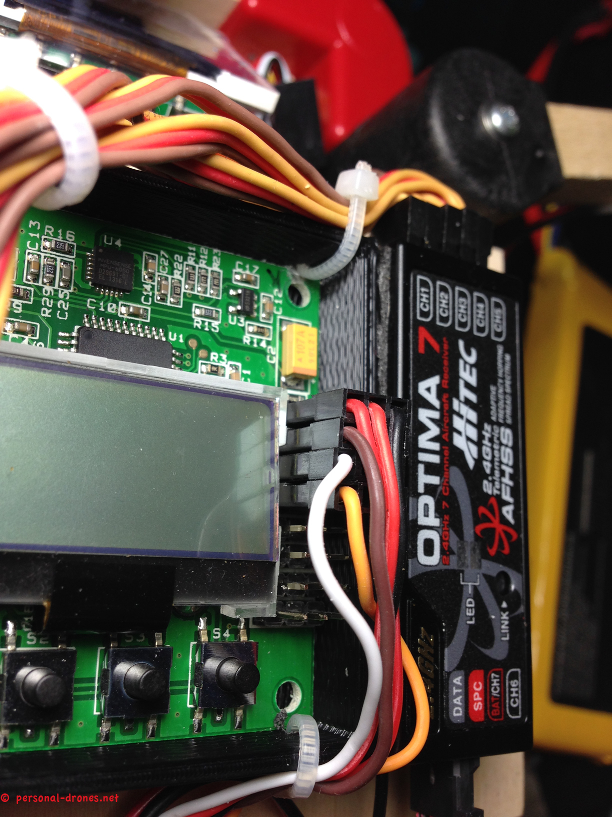
The final thing is to attach the receiver to the board enclosure, the enclosure has a nice area just for that, and then wire the receiver to the KK2 board.
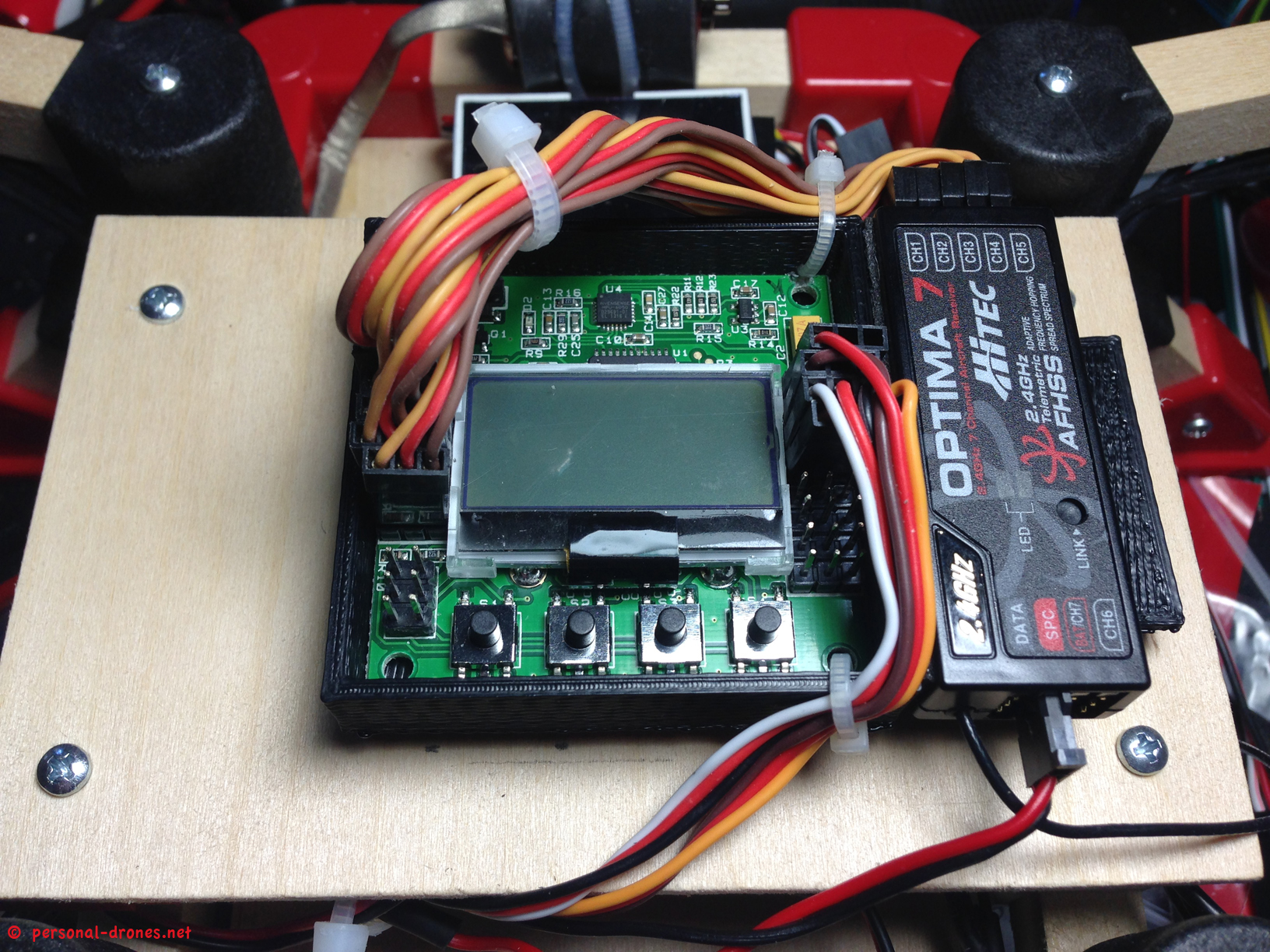
The pins column on the left side of the board are those for the receiver channels. On the board, the rows of 3 pins correspond to, from top to bottom
KK2 pins:
– aileron
– elevator
– throttle
– rudder
How you connect those to the receiver depends on the order of the 4 channels on the receiver and how they are programmed in the radio. For my Aurora 9 radio, the default is the same as the the KK2 board, so the order of wiring, from top to bottom on the board, is 1 2 3 4 5.
5 will be used for the AUX, typically to turn on and off self stabilization on the board.
Detailed programming of the board is beyond the scope of this article. I should say that I flashed the board, a KK2.1 board, with firmware version 1.14S1. The software for flashing can be downloaded here and this USB ASP cable is needed to flash the board. Instructions are easily found on youtube, however if you would like these topics covered on this blog or have any specific question feel free to ask by making a comment below.
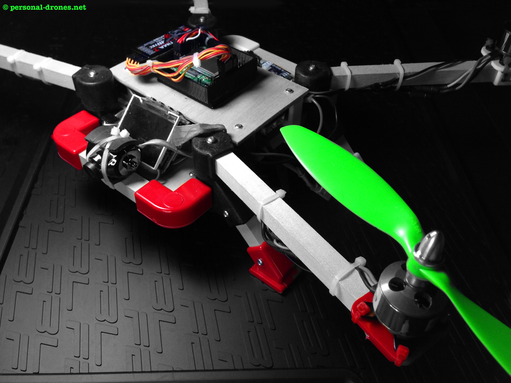
So here is the final assembled quad:
I have flown it for a few minutes now and I am impressed with the stability “out of the box”. Without tuning anything on the KK2.1 board, except performing the accelerometer calibration and setting the correct motor layout for an X quadcopter, the quad is surprisingly stable and ready for some mission.
Final considerations
I am very happy with this build. It was a full DIY experience, more that with other frame systems, mainly because of the wood component, that is so easy to shape and therefore allows for so much flexibility.
Pros
Main material is wood, in simple shapes. So your creativity is the limit for what you can create with the lugs system
The arm lugs, as extensively discussed, allow to decide the angle of the arms at will, and to change the angles at any time depending on the requirements, for example the field of view of the camera that you are using or the desired flight characteristics.
The two plates system is very flexible, you decide size and shape of the plates to fit your equipment optimally.
Quality: the quality of the components is excellent. The arm lugs, center of the system, are sturdy nylon pieces and are clearly done to last
A number of interesting little accessories are provided that make life easier, such as the KK2 board enclosure and others
Cons
Main material is wood. The resistance is limited. How will these wooden arms stand a crash? Probably on a hard crash they will break much easier that say, DJI F450 arms. On the other hand, replacement is easy and inexpensive. I would probably not use my quadlug quad for aggressive acrobatic, crash prone flight, there are better frames for that. I would like to see the Quadlugs system extended to other stonger material so as to be able to choose. For instance a wood core but stronger arms, indeed a weak spot in case of crashes, could be considered.
Comparison to RotorBits
How does this system compare with other modular systems like the recently introduced Hobbyking’s RotorBits? A RotorBits quadcopter frame is under way for testing. However from what we can see from the pictures on the Hobbyking site, there are some relevant differences. There is no piece equivalent to the arm lug, with variable orientation. This alone makes the system much less attractive than the quadlugs system. The angle of the arms is determined by the insertion points on the frame itself. The frame is plastic. So it looks like it would not be so easy to build your own plates, with custom arms orientation, and more importantly with a custom shape and size, with a RotorBits system. Conversely, this find of flexibility is in the very nature of the Quadlugs system. This said, we will have a close look at the RotorBits system for a first view comparison of the two products.
I hope that this build and review article was useful in getting you familiar with the Quadlugs modular multirotor building system. I will be happy to answer any question or provide advice on your own build, just post a comment below.
You can also get in touch with the Guys at Quadlugs directly. They are a friendly team and surely will be happy to provide advice on their products.
Stay tuned on our Blog for some video footage from the Quadlugs quad in the near future!
Quadlugs modular multirotor system review
3 thoughts on “QUADLUGS MODULAR MULTIROTOR SYSTEM QUADCOPTER BUILD AND REVIEW – PART 4”