In part 1 and part 2 of this “build and review” article I made a general overview of the Quadlugs modular system and showed how to fully assemble a 480 mm frame. The whole process takes a few hours, especially the first time, when you have to figure out a number of things. I am sure that on my second build (there will definitely be one) things will go much faster. Also, since the things I had to figure out are all included in this review, if you follow instruction closely, and also check out the Quadlugs build videos, then the build of the frame should be really straightforward. Speed will also depends somehow on your personal DIY skill, although I promise that putting the frame together is something that anyone can do.
The frame is now ready, see part 2. Only the top plate remains to be secured in place, however this will be done after all the electronic equipment is mounted.
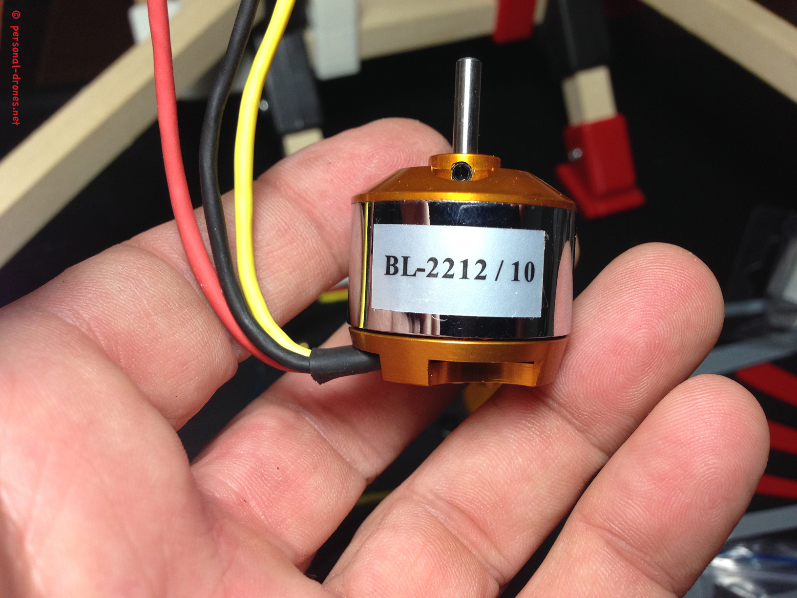
Let’s start by fixing the motors to the motor mounts. In this case, the motors came without the needed 3.5 mm gold connectors (link) pre soldered to the wires, so I had to solder the connectors myself:
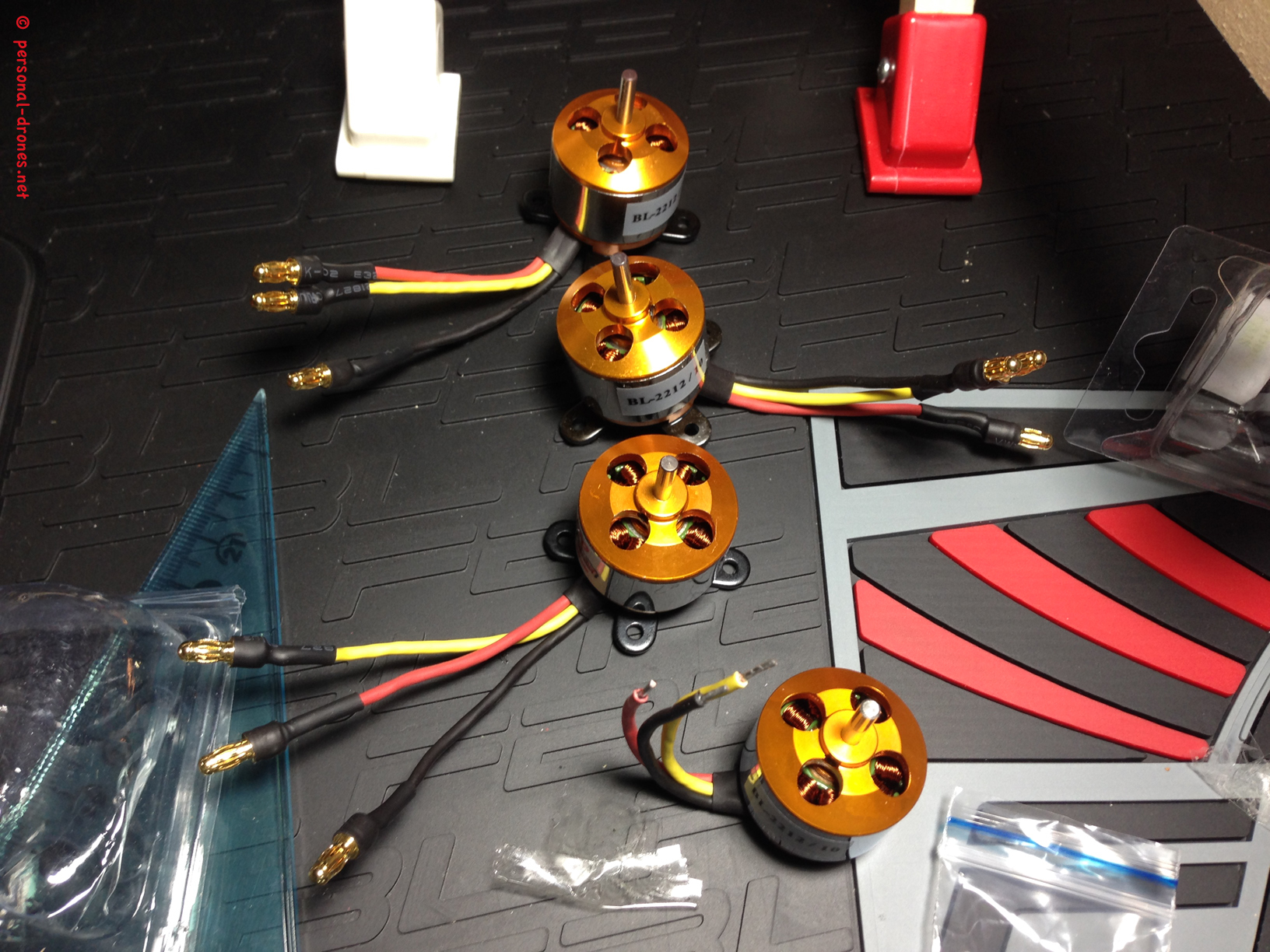
As you see in the picture above, the motors (see the 3 with connectors) have been screwed to their cross shaped base. Base and screws come with the motors.
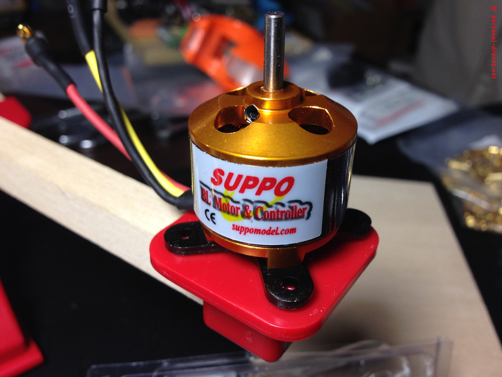
Now as unusual as this might seem, in the educational videos Quadlugs suggest that you zip tie the motors to the motor plate lugs rather than screwing them. I did that and indeed it works great! Just make sure the zip ties you use are not too crappy.
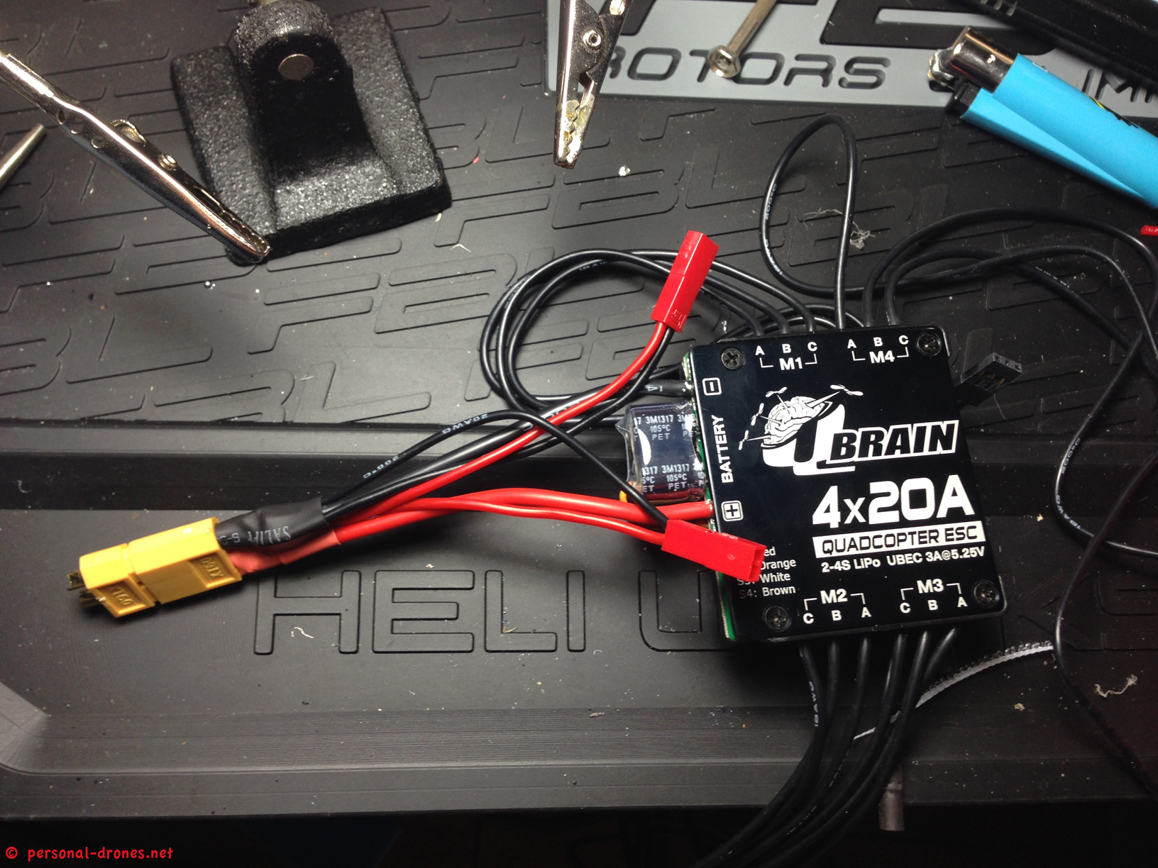
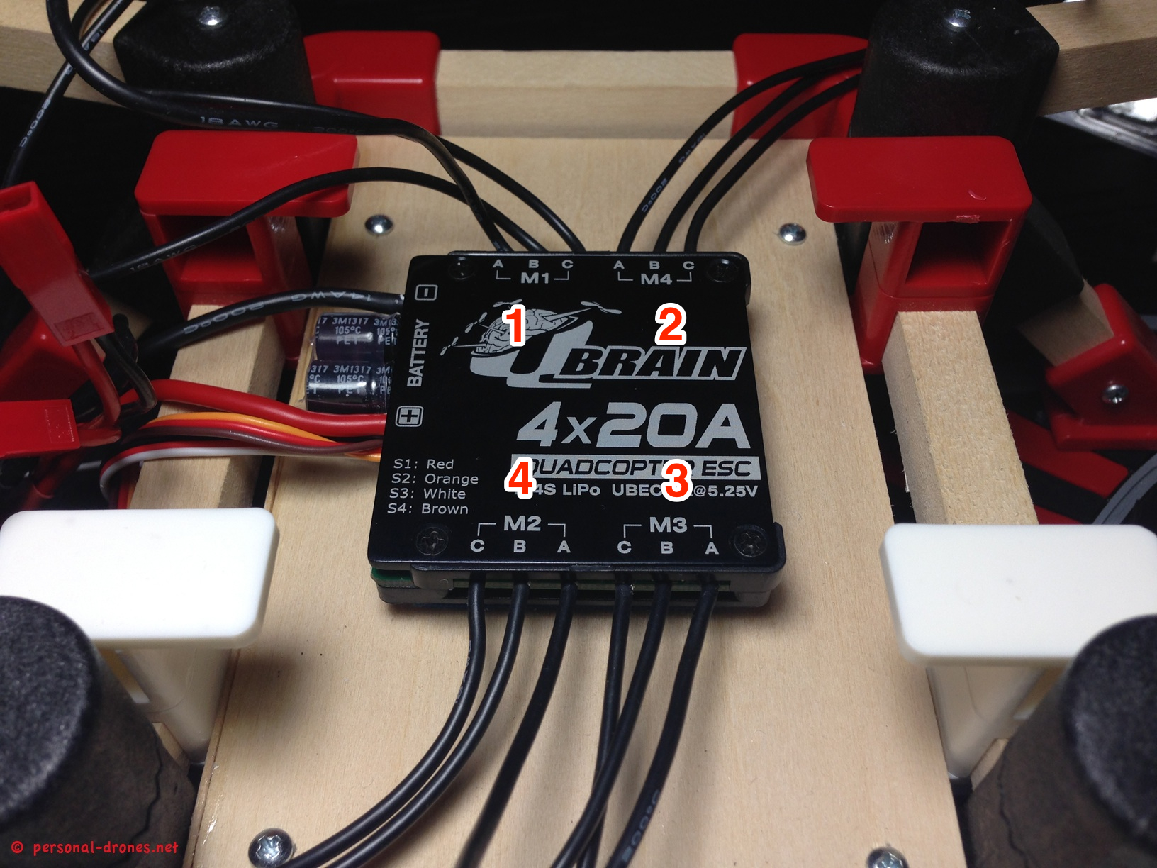
Once the 4 motors are in place, it’s time to fit the ESC block in place. As recommended by Quadlugs we are using the 4 in 1 Q-Brain Quatro ESC system from Hobbyking.
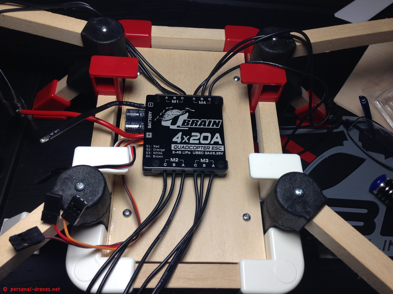
This works beautifull, however you have to take note of which ESC (they are numbered from M1 to M4) goes to which motor.
Now since we are using a KK2 board flight controller for this build, motor numbering goes like this:
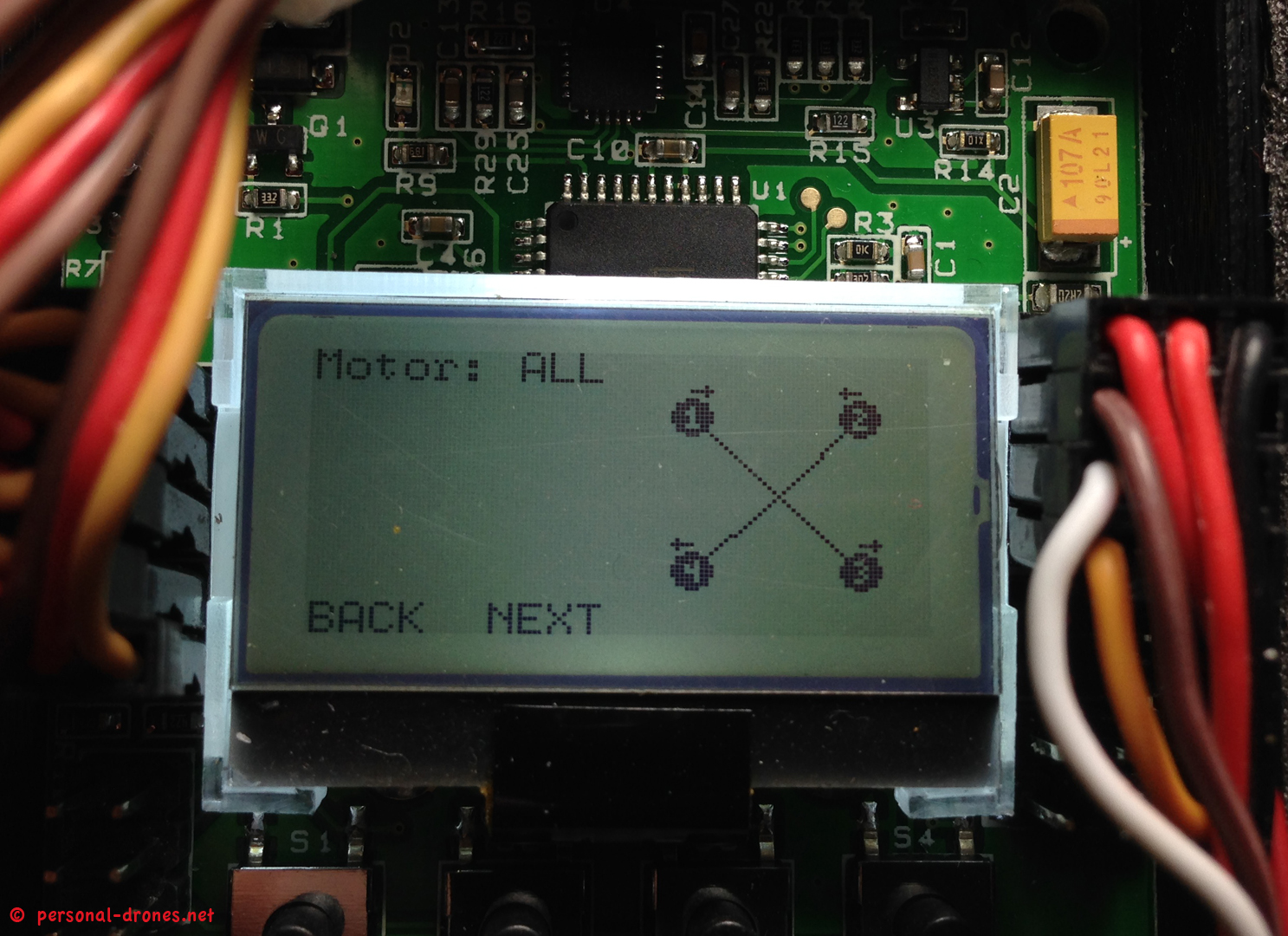
So if we have the quad in front of us, facing ahead (rear arms near to us), front left motor is number 1, front right number 2, and continuing in a clockwise direction, rear right number 3 and rear left number 4, see the picture above. We also learn from the picture that motors 1 and 3 will have to spin clockwise and 2 and 4 counter clockwise. So care will be take during the build that the direction of motor spin is correct and the correct propeller type is selected for each motor (CW or CCW).
So now back to the Q Brain ESC, the ESC numbers WILL NOT correspond to the motor number. When you position and wire the ESC cables, just take note of which ESC number you are connecting to which motor. Because of the way I have decided to position the ESC block, the numberings will be as such:
ESC Actual Motor (for KK board)
M1 Motor 1
M2 Motor 4
M3 Motor 3
M4 Motor 2
This leaves the power cord on the left side of the quad. Also scroll down for an explicit picture on this.
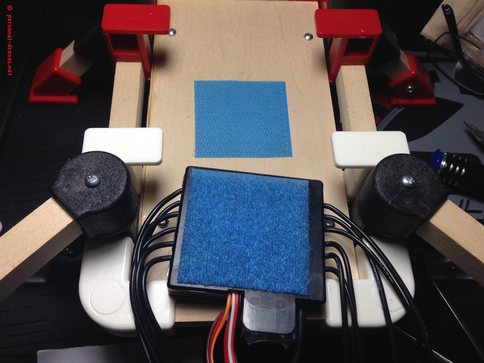
Now let us fix the ESC block to the frame with some velcro strap:
Preparing the quadcopter power system
Before we fix it in place though, we have to care about the connector to which the battery of the quad will be attached later on. This connector (I selected an XT60 connector) has to be soldered to the Q Brain power wires. Since this will be the primary source of power for the quad, you might want to add at least a couple of JST connectors in parallel here, to power some additional equipment. I did use those additional JST in this build to attach:
- The front and back leds
- The SPC cable of my Hitec Optima 7 receiver that allow to have the current power broadcasted to the radio. Great simple telemetry feature available in the Aurora 9 radio that I currently use
The video/FPV system is powered through the battery balance cable as I will show later on.
The following picture shows how to solder the XT60 connector (yellow) to the Q Brain power wires together with two accessory JST connectors
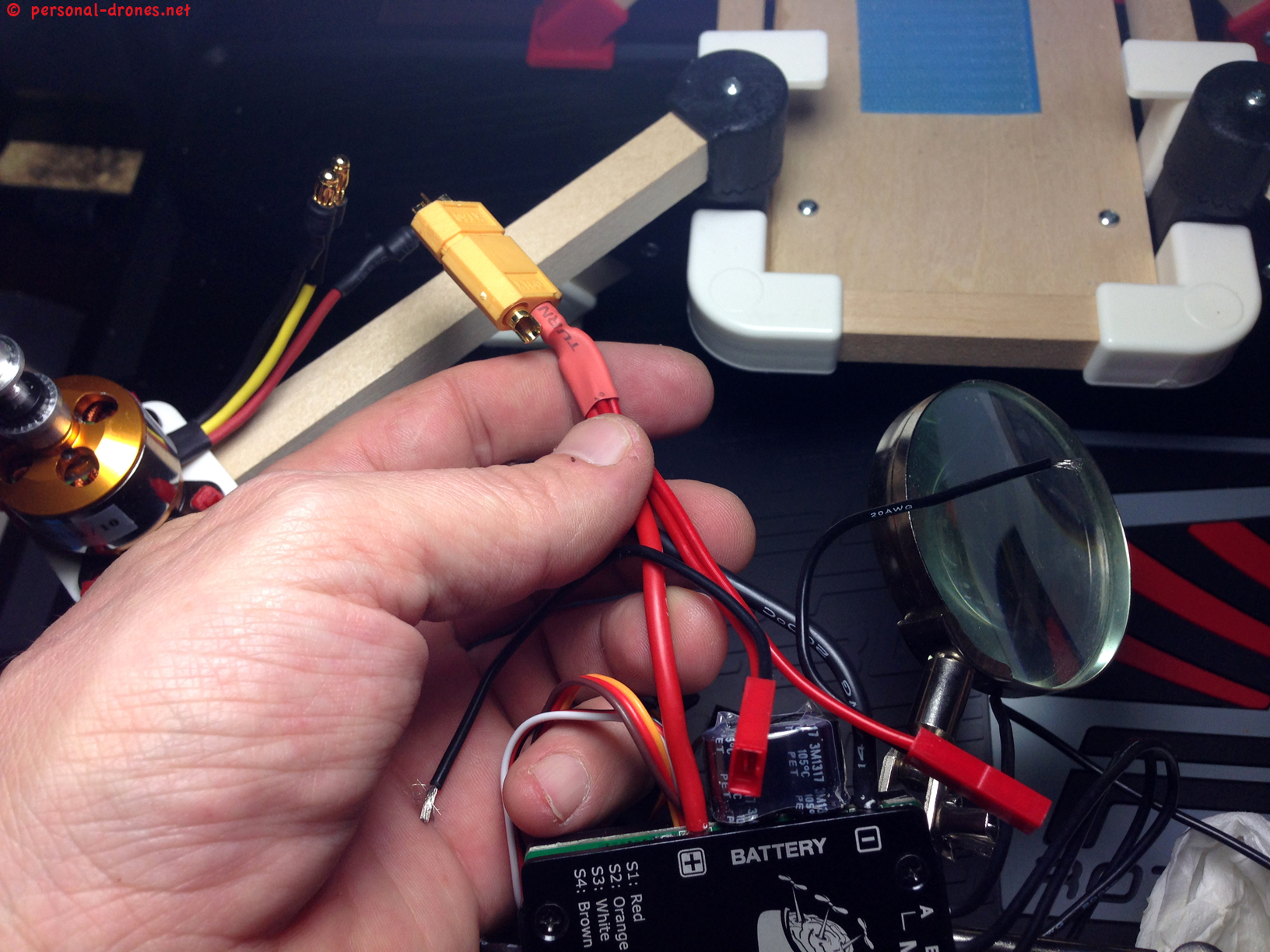
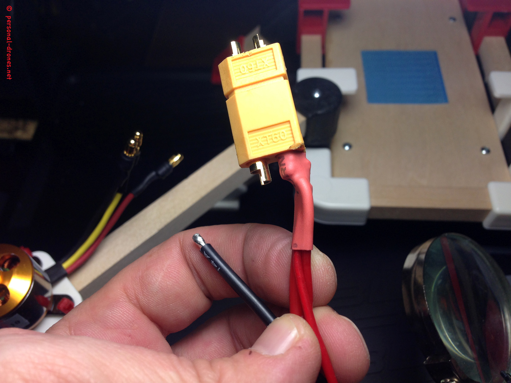
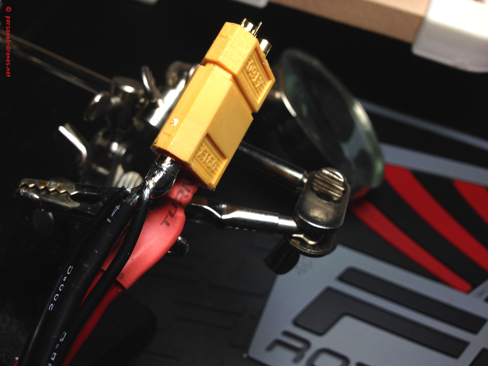
Please note in the picture above how, during connector soldering, while I soldered to the female, I left the XT60 male connector fitted into the female. This helps to prevent deformation of the plastic during the heating generated by soldering and is a good general practice in soldering XT60 and other connectors.
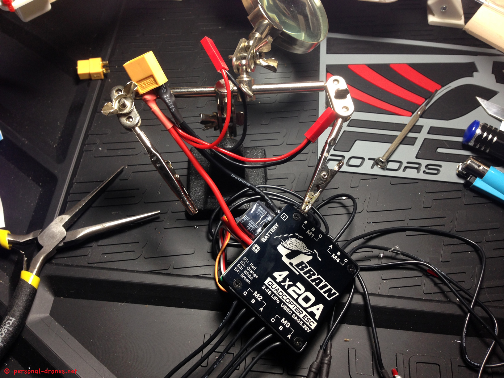
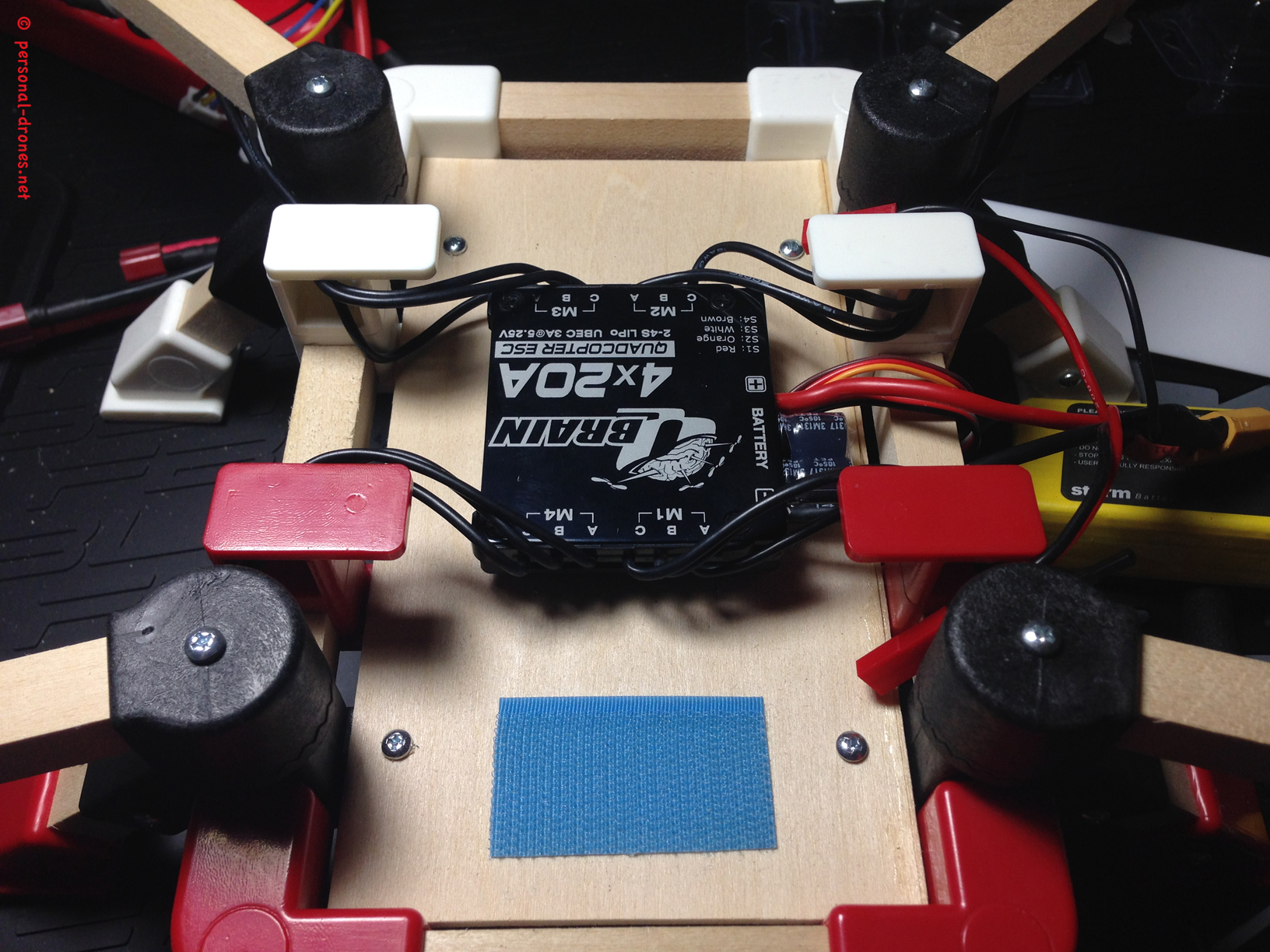
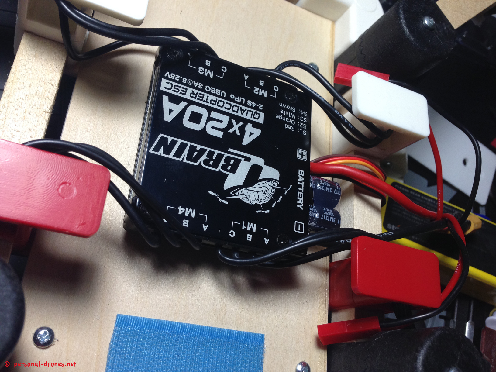
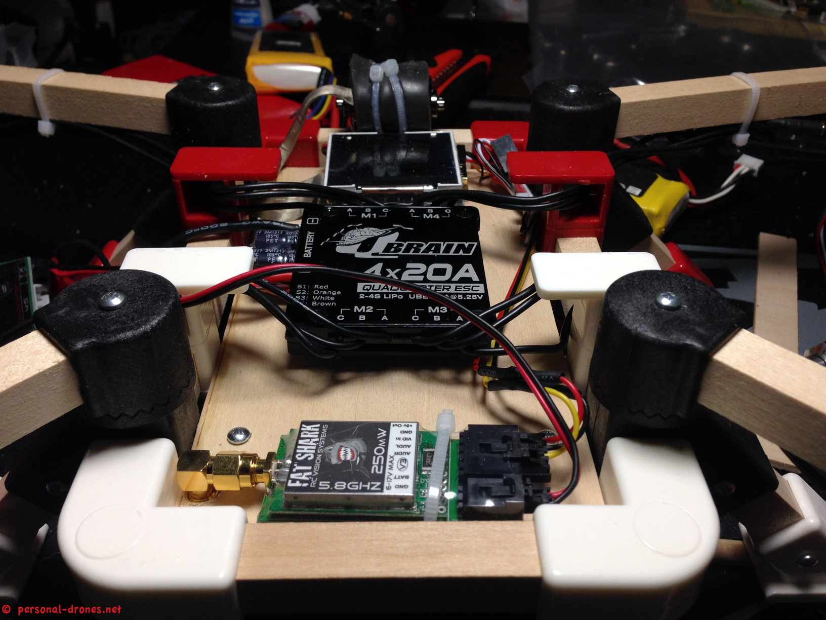
And finally here is the Q Brain ESC block mounted to the frame. I also annotated in red the numbering of the motors for the KK2 board, take note for later on when we will have to wire the Q Brain ESC signal cables to the KK2 board.
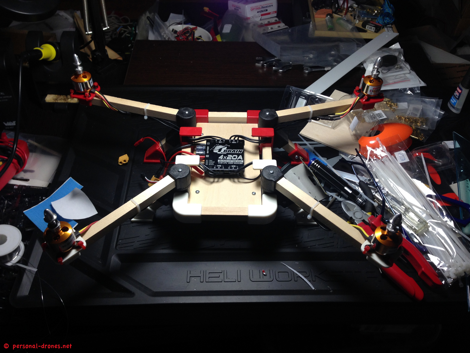
Please note that the mess you can spot in the pictures is a creative mess, out of which marvelous flying machines emerge. After each building session the required amount of time is devoted to putting back every tool to it’s place is dedicated. However the creation requires a phase of creative chaos.
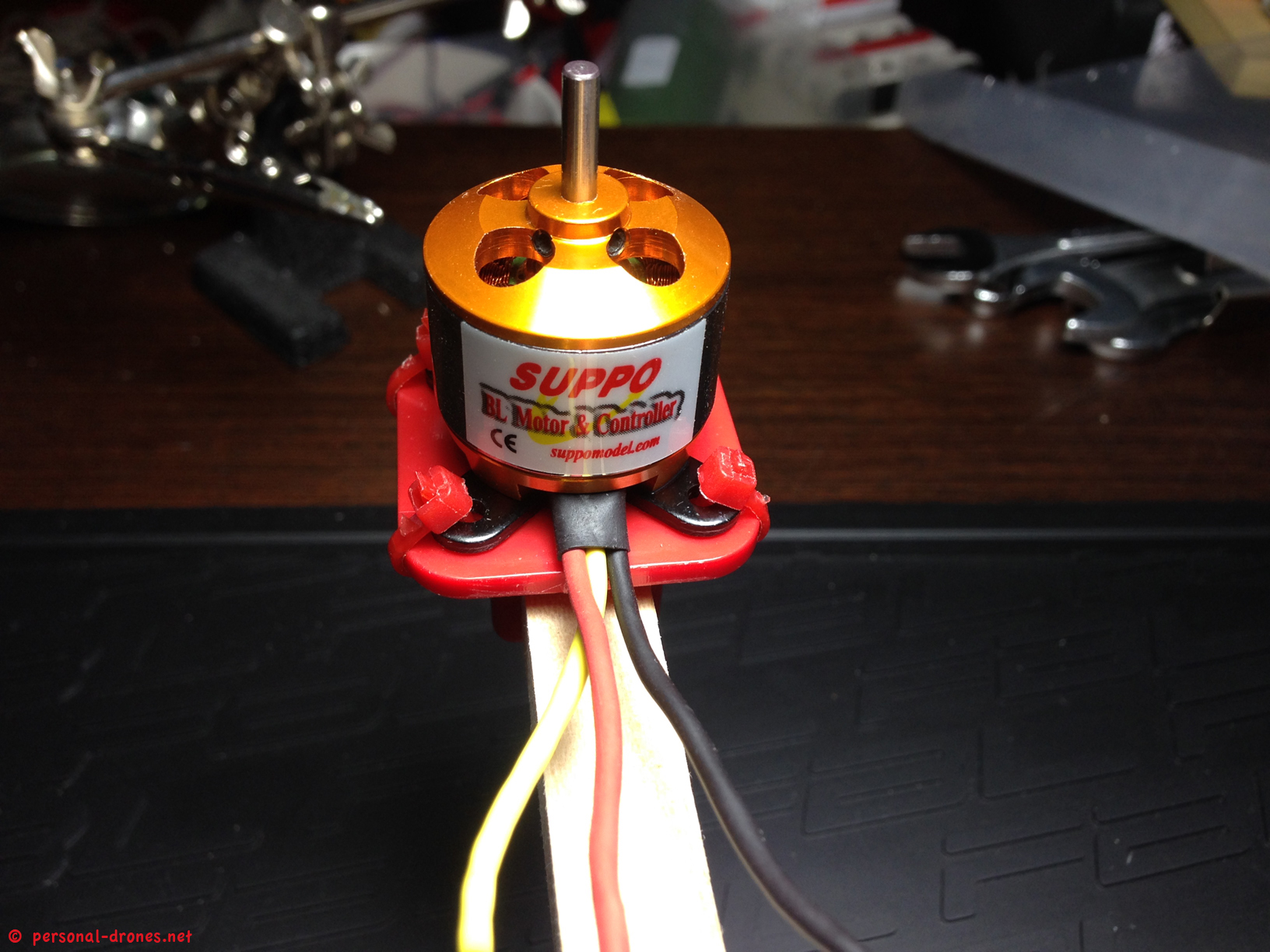
So how do you connect the 3 motor wires to the respective 3 ESC wires? For now, we have to make sure that the center wires of the motors, which for Suppo motors are the yellow ones, are wired to the center wire for each “triplet” of wires. The center wires are labeled as B on the ESC block, so you can’t go wrong, find them highlighted in the picture below.

Then for each motor we just connect randomly the C and A wires of the ESC to the red and black wires of the motor.
Then, when we first test motor rotation, we will have to check if the direction for each motor, as detailed above in this article, is the expected one. If not, we switch the red and black wires position with respect to the C and A cables of the ESC, and the motor rotation will be inverted. Conversely, it is for sure that the center wire of the motor will attach and remain attached to the center wire of the ESC.
If anything is complicated or you feel you are not fully understanding those reasonings, feel free to comment or ask a question by using the comments form below the article and I will do our best to help out.
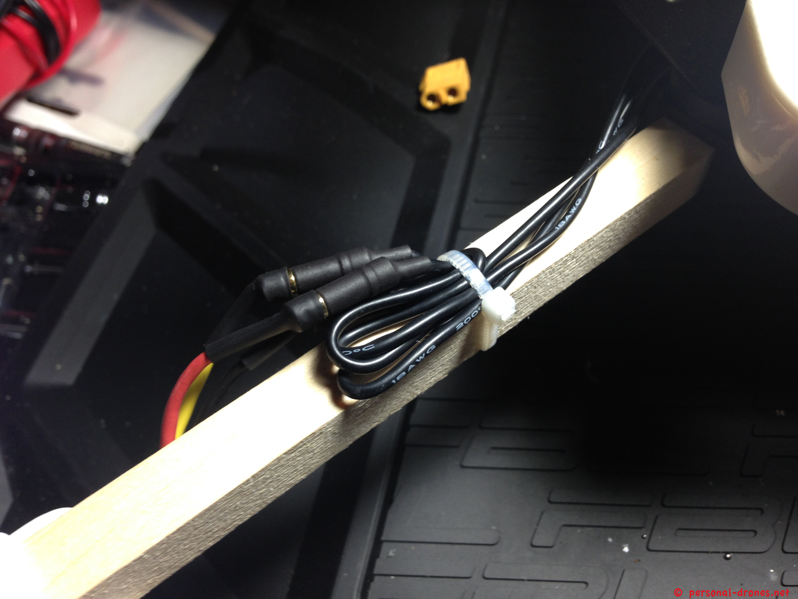
Once we are sure the wiring is correct, because we have tested and adjusted motor direction rotation, we can can secure the ESC/motor wires to the frame by using zip ties as shown below:
What happens to me is that I find myself securing cables, to then realize I have another cable to add. So zip tie is cut down, the new wire is passed and a new zip tie is put on. I guess this is kind of normal and helps very much anyway in keeping the build “compact” during the work. So a zip tie can well be a temporary thing to be used while building, to be then replaced by a final one. I suggest you find a cheap source of good quality zip ties. I found a nearly endless supply in a Chinese shop near to my house, one of those generic Chinese shops that sell everything, from home supplies to consumer electronics, usually at very convenient prices. Well in a corner of this shop, after months of sourcing the ties on e-bay at unreasonable prices, I found them. Find a source and get a solid stock. An RC model builder can’t have enough zip ties around.
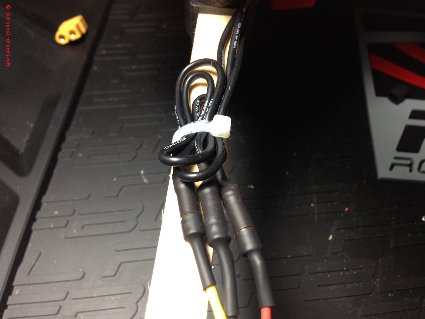
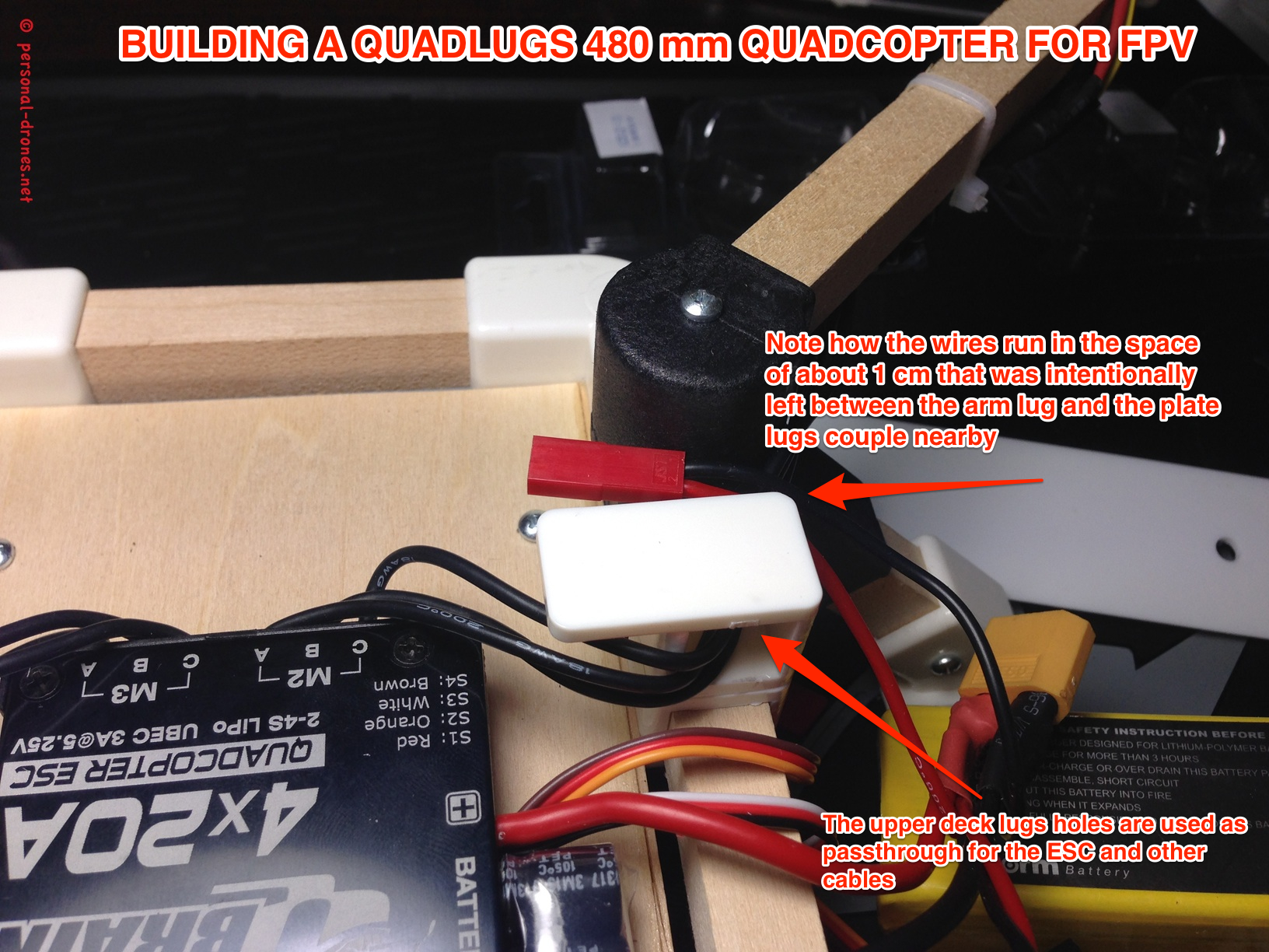
See how the wires make a turn to be shortened a bit. Please take a note of an important decision I make for this build. That is to leave a space of approximately 1 cm between each arm lug and the plate holding lug nearby, in order to leave some room for wires to pass in this space. This will also leave a clean opening, between the lower and upper decks, on each side, leaving some accessibility and leading to a cleaner and nice build, where the wires have their own natural channels to flow in the frame.
In particular I have then used the upper lug of each plate holding lugs couple, the one that is hollow with no wood inside and will hold the upper plate, to run the ESC wires. A picture will illustrate this much better that all this confusing explanation:
Now that we have the power system in place we can start thinking about the control board and the video and FPV equipment. It’s a good idea, at this time, to have a final plan. What I mean by this is that since the board will go on the top deck, it is a good idea to first position all the additional equipment needed on the lower deck. You might need to pass wires to the side of the ESC block for example (see how the left side in the picture above is nicely empty and ready to host some wires).
All this work on the lower deck is much more comfortably done without the upper deck on the way. This is why I decided to first mount the FPV equipment and only after, the upper deck with the KK2.1 board and the receiver for the radio.
The FPV Setup
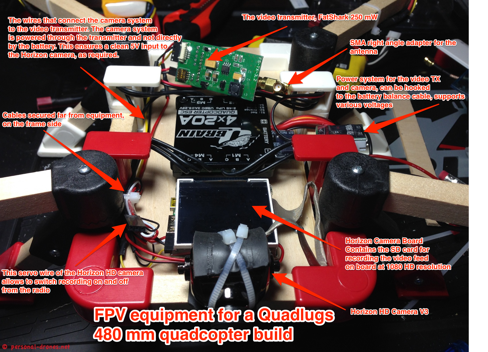
Let’s now examine the FPV setup. This will of course vary a lot depending on the equipment you have available or want to use. The number of pieces can vary, for instance the Horizon HD camera I am using here have a camera and a distinct board for recording, and so the arrangement. For instance you can easily mount a GoPro gimbal on a Quadlugs build. Check out the Quadlugs 540 mm “Camera quad frame kit” that looks perfect for this kind of application.
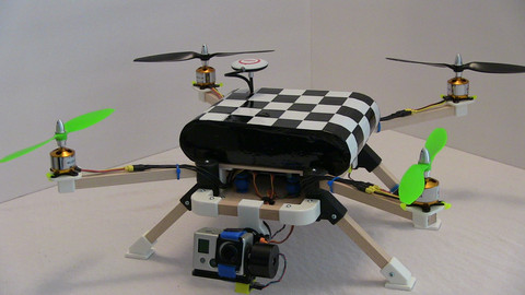
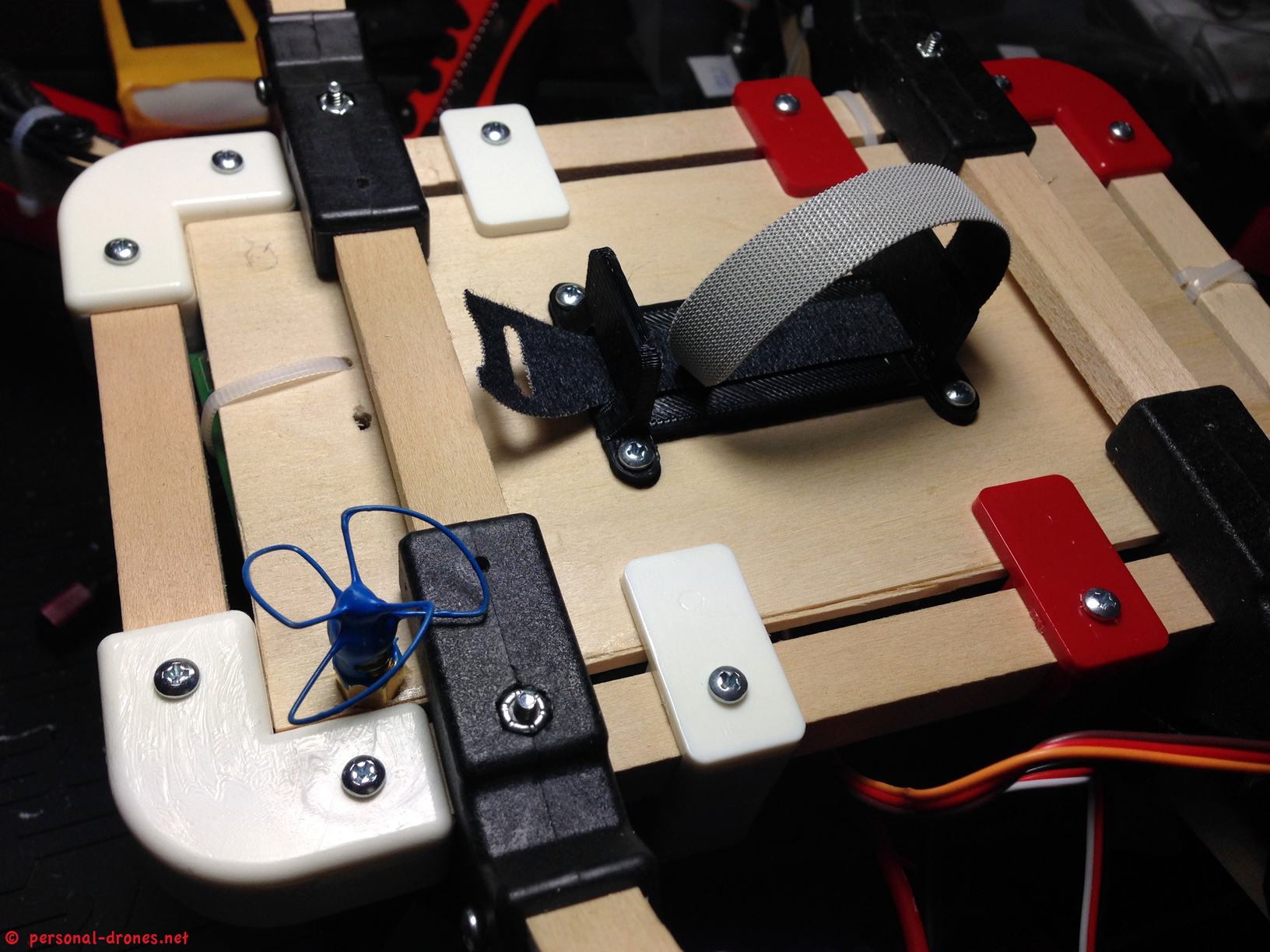
Ok back to our build, this picture should provide a rough idea of how the FPV equipment was mounted.
In the photo above the video transmitter antenna is still not in place. Let’s see how it was put in place:
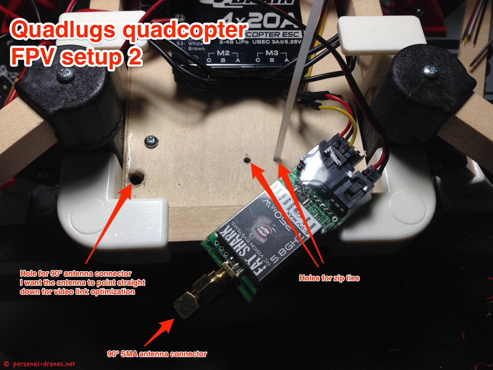
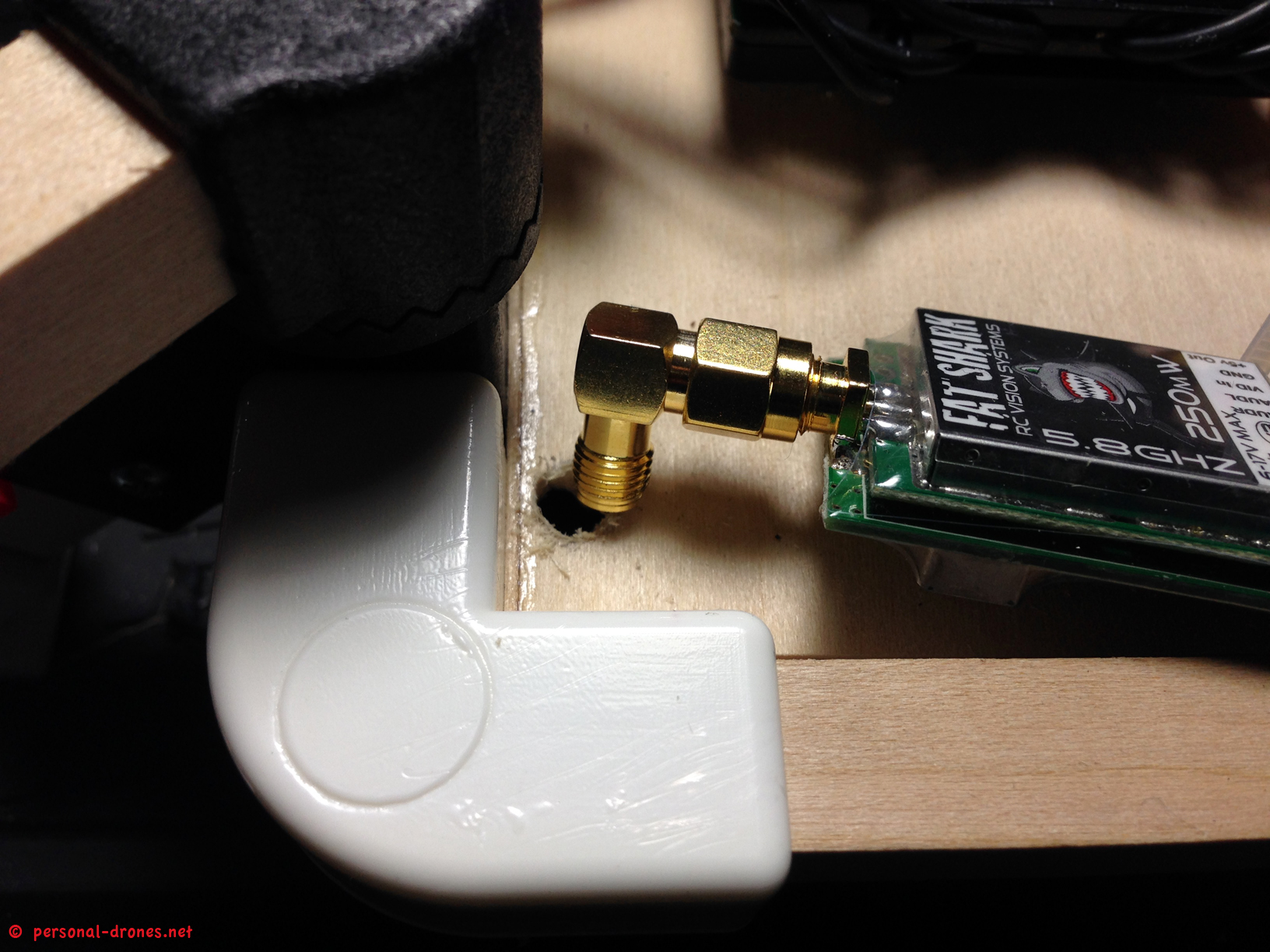
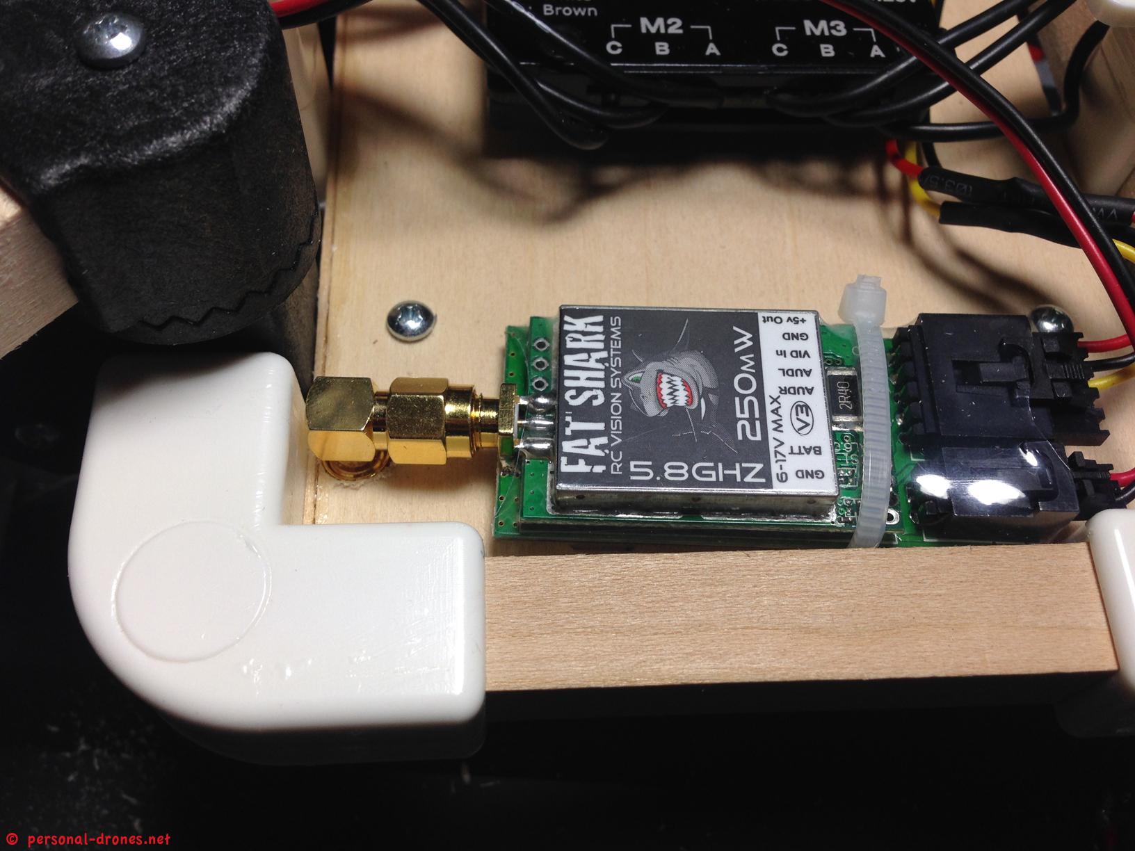
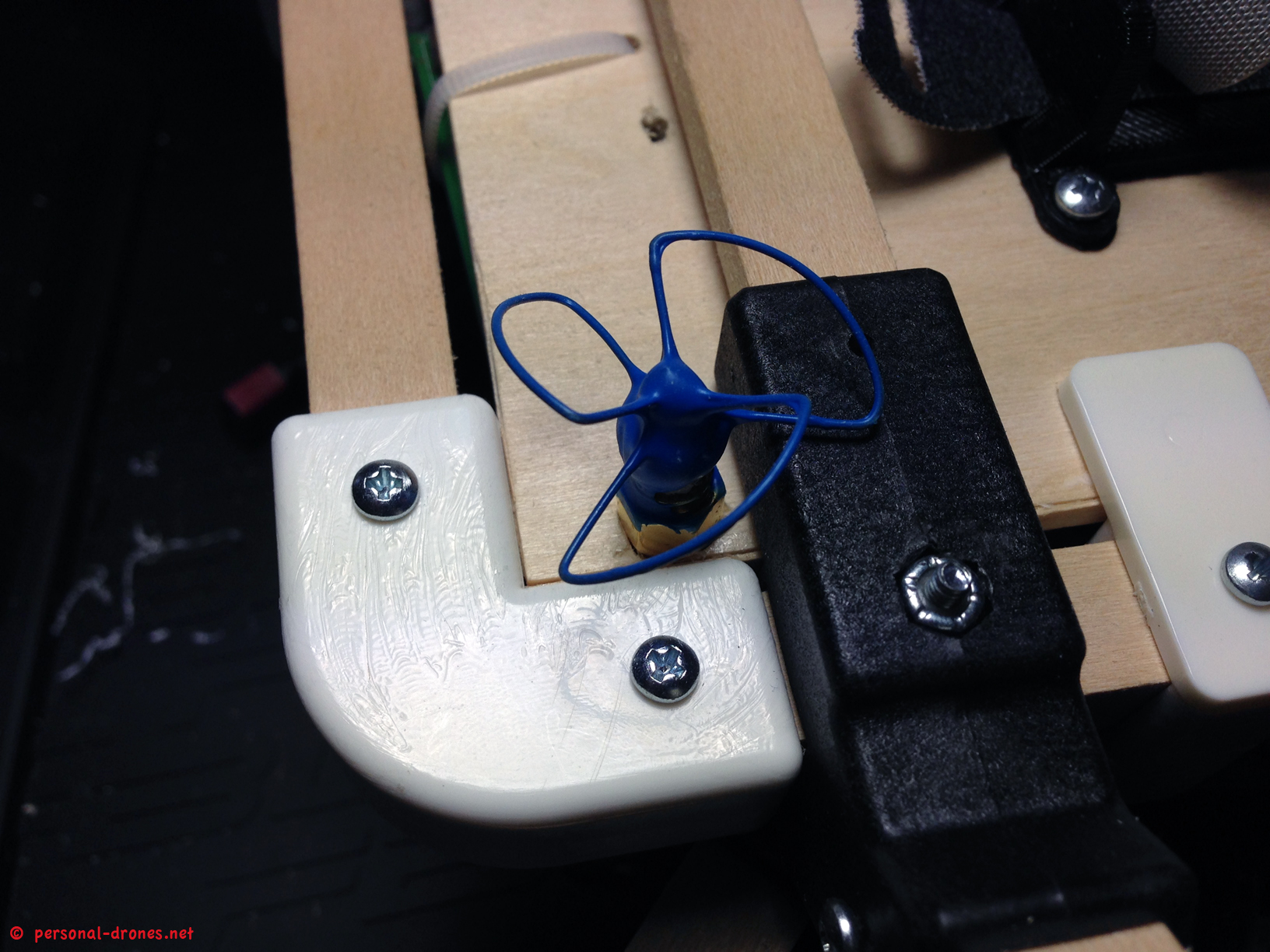
And here is the video antenna. Since as noted above, the landing gear only leaves slightly more than 4 cm clear below the frame, I have selected a very short, yet powerful IBCrazy Bluebeam antenna, sourced from Ready Made RC.
We are now ready to fix the upper deck in place, with KK2 board and radio receiver. We will discuss this in detail in part 4 of this article.
For any comment or question do not hesitate to post by using the form below.
Stay tuned on the Personal Drones blog for the follow up of this article!
Quadlugs modular multirotor system review
3 thoughts on “QUADLUGS MODULAR MULTIROTOR SYSTEM QUADCOPTER BUILD AND REVIEW – PART 3”