The Mobius camera is the big brother of the 808 camera. It features 1080HD quality, a wide angle lens, easy of use, light weight, storage on SD card. I recently got one and decided to try an FPV setup by using this camera together with a Fat Shark Immersion 250mW 5.8GHz video transmitter.
Since it took me a little while to figure out how to establish a correct cable connection between the camera and the transmitter, I thought I would share here how I did it, it’s an easy and quick FPV setup.
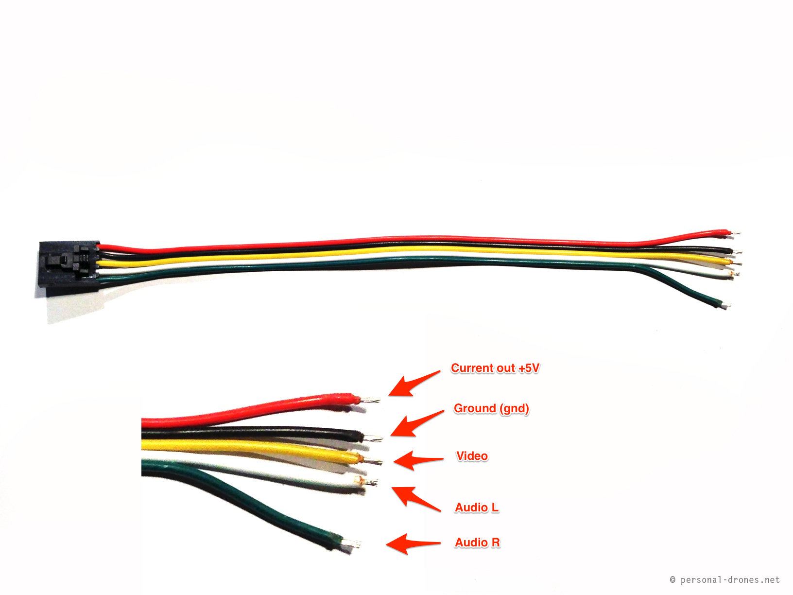
First let’s have a look at the immersion style cable that comes with the transmitter:
Immersion style video transmitter cable
In this little tutorial we will limit ourselves to connect the video component only, constituted by two wires: the video wire (yellow) and the ground (gnd) wire (black). However, by following a similar approach, it is easy to also hook up the audio and power wires, so as to provide power to the camera directly from the battery of the aircraft.
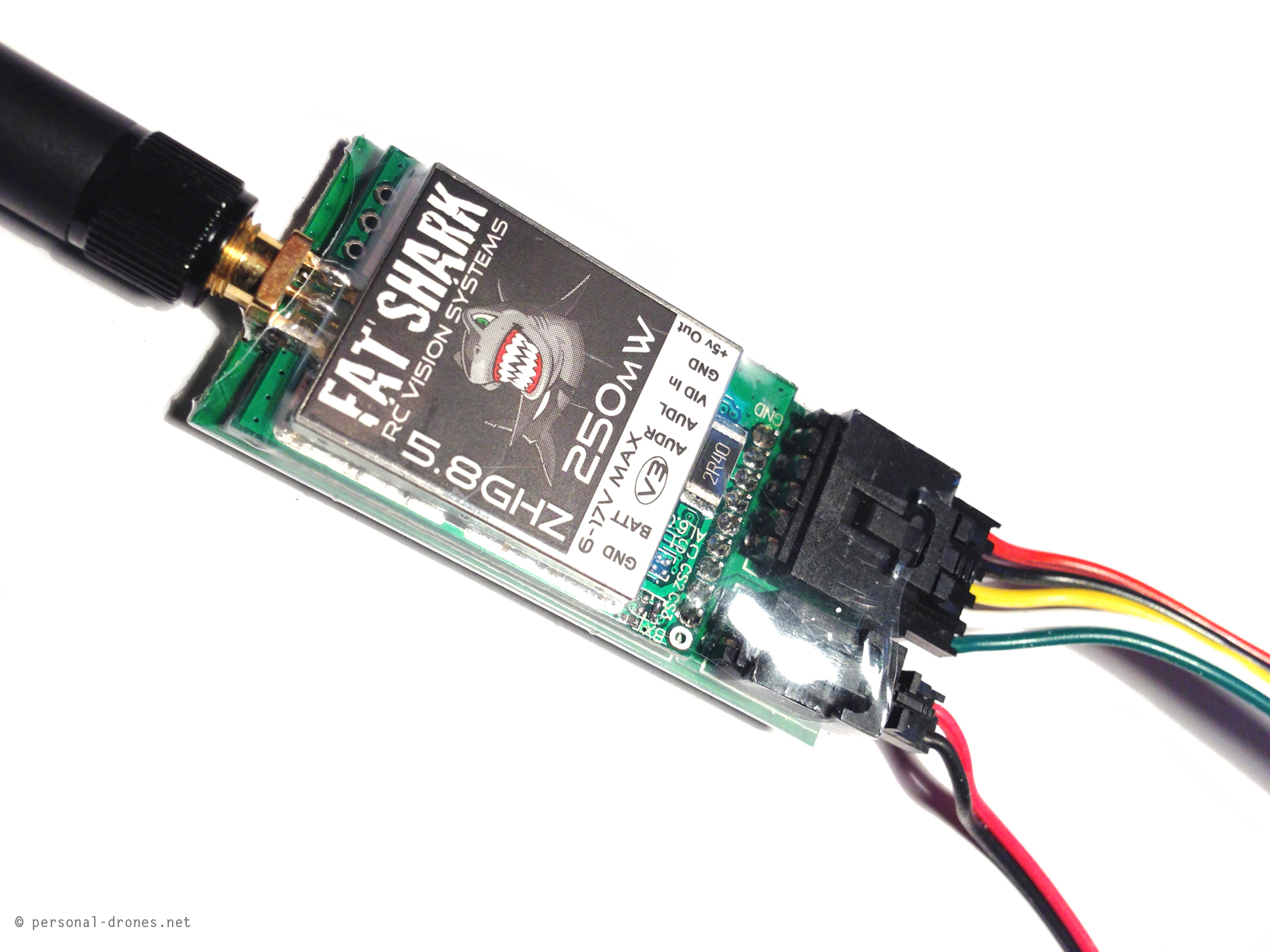
This is the transmitter cable connected to the Fat Shark video transmitter:
FatShark 250mW, 5.8GHz video transmitter
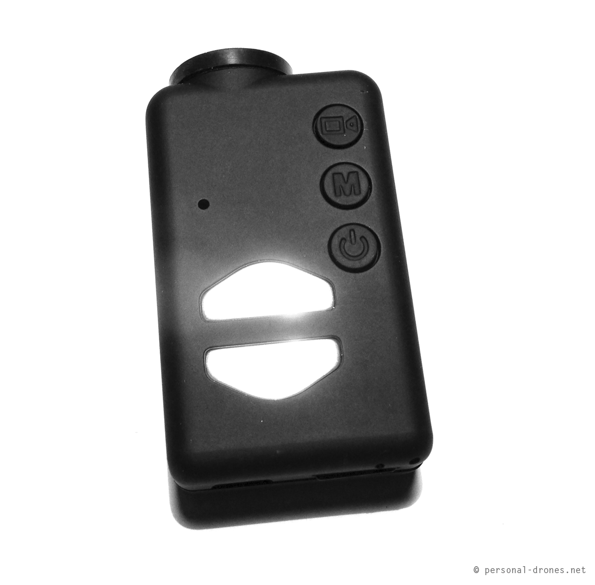
For the mobius camera
Mobius camera
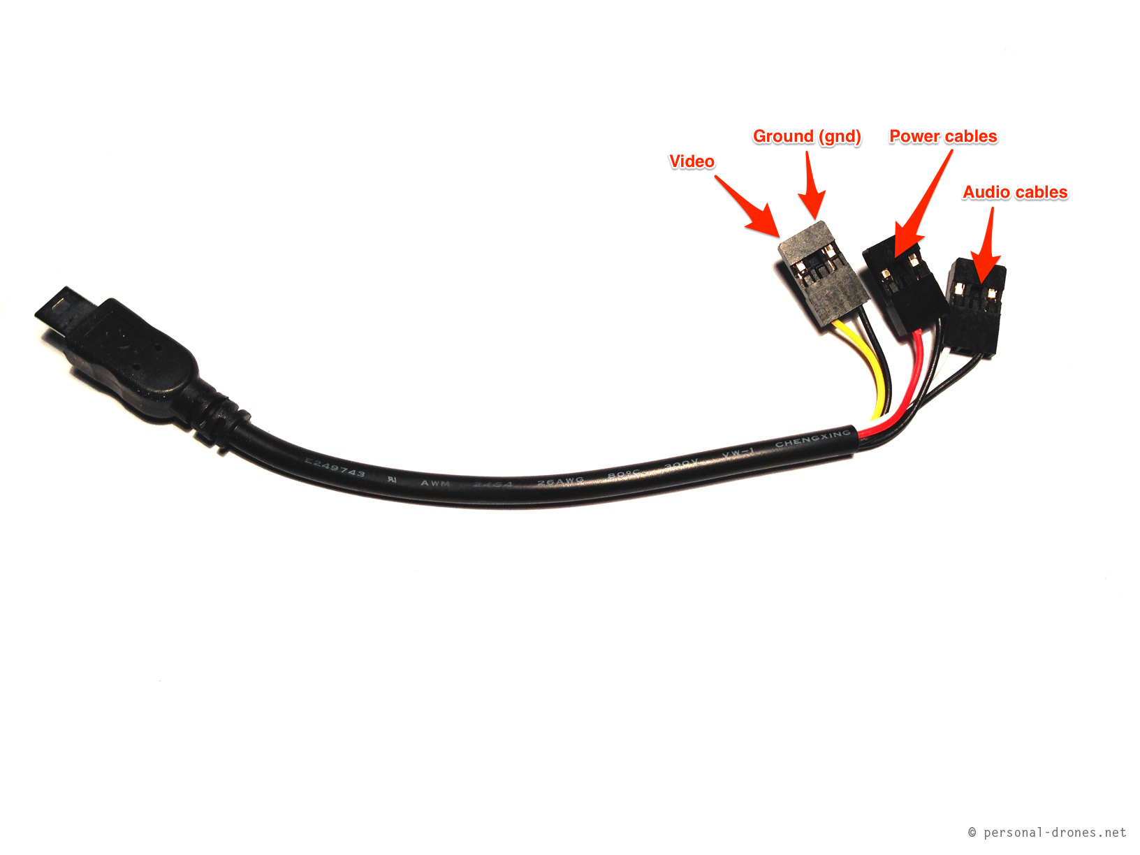
it is easy to buy a special usb cable for video and audio out and power in. It looks like this:
Video out usb cable for mobius camera
What we want to do is connect the video and ground wires of the USB connector to the video and ground wires of the transmitter cable. We could simply cut out the connector for the video and ground wires from the usb cable and solder them directly to the corresponding wires of the video transmitter cable. However I opted for a little more flexible setup that would leave the usb cable intact, for an eventual different use in the future.
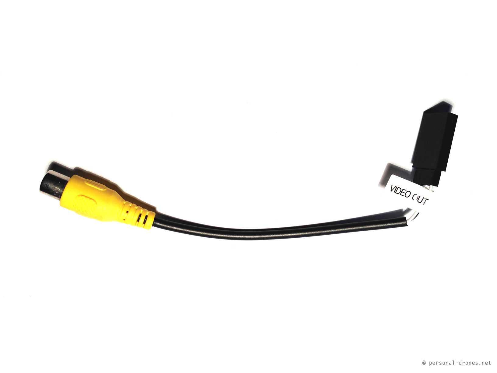
The mobius cables set (optional purchase) not only includes the usb video out cable (photo above) but also an RCA video cable that can be connected to the video connector of the usb cable. It looks like this:
Video cable for mobius camera
In the cable in the photo above the video wire is white. I actually used a very similar cable in which the wire is yellow instead.
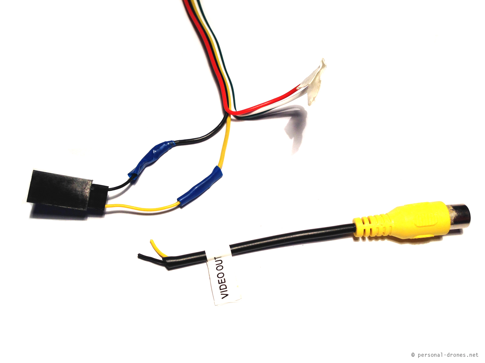
What we will do is to cut out the connector from the video cable and solder it to the corresponding cables on the video transmitter cable. Here’s the final result:
Job finished. All you have to do now is connect the camera to the usb cable, then the video connector of the usb cable to the newly attached connector to the video transmitter cable.
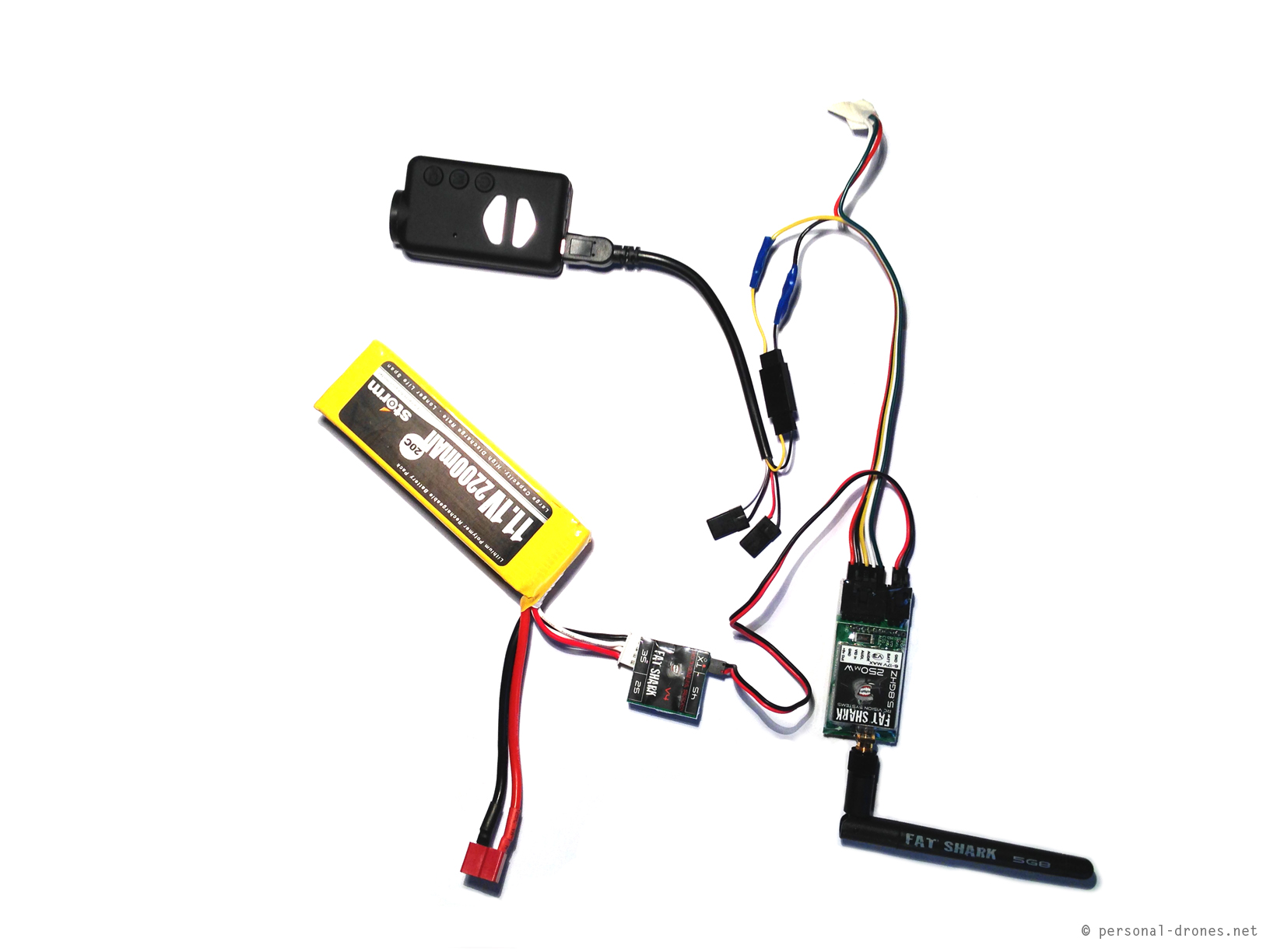
This is the final complete FPV setup:
Mobius camera connected to the FatShark 250mW video transmitter, complete setup
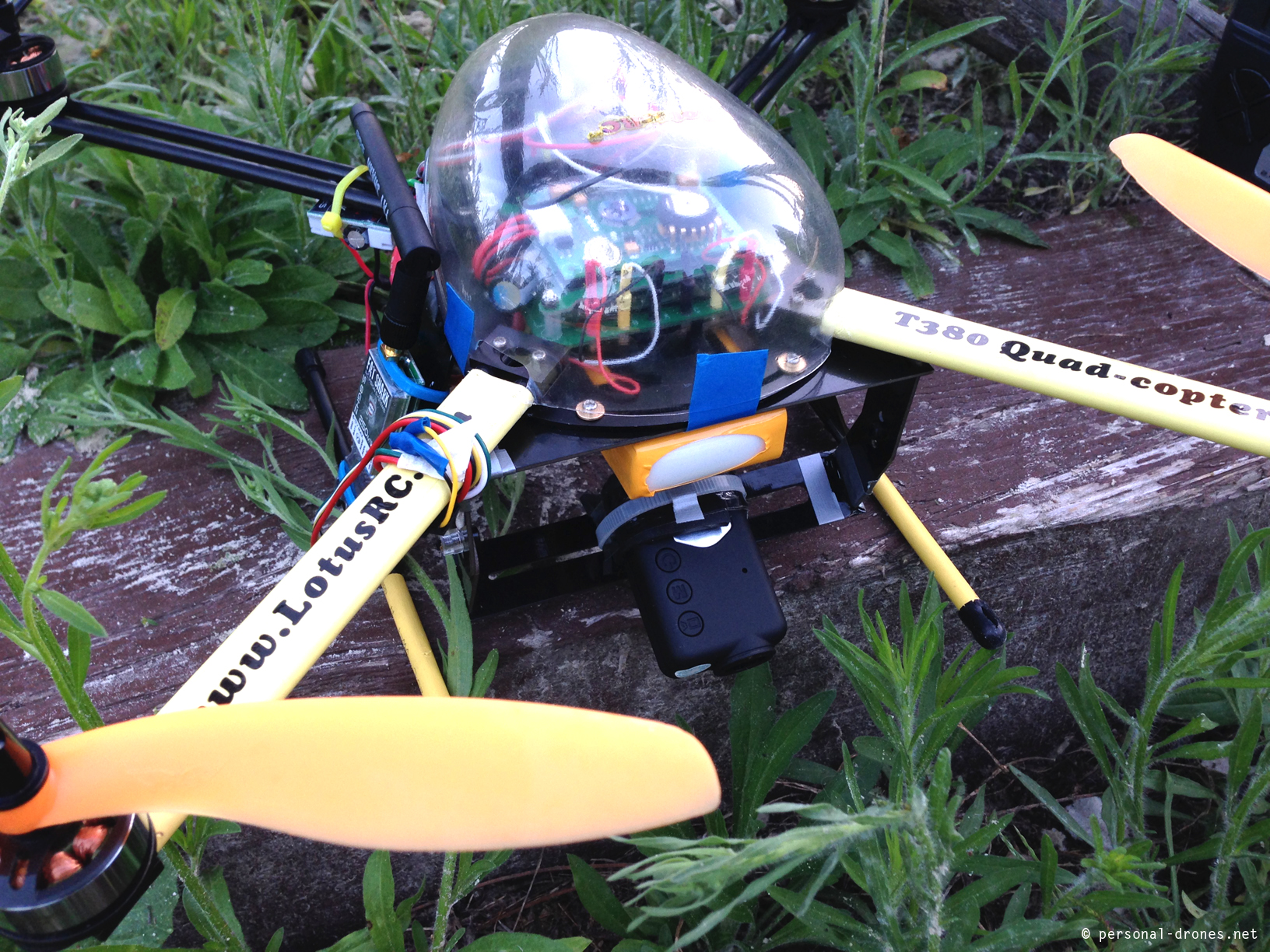
This is a first test mount of this setup on a Lotus RC T380 quadcopter.
Loutus RC T380 equipped for FPV with Fat Shark transmitter 250M and Mobius camera
Questions or comments most welcome.
Edit April 25, 2014
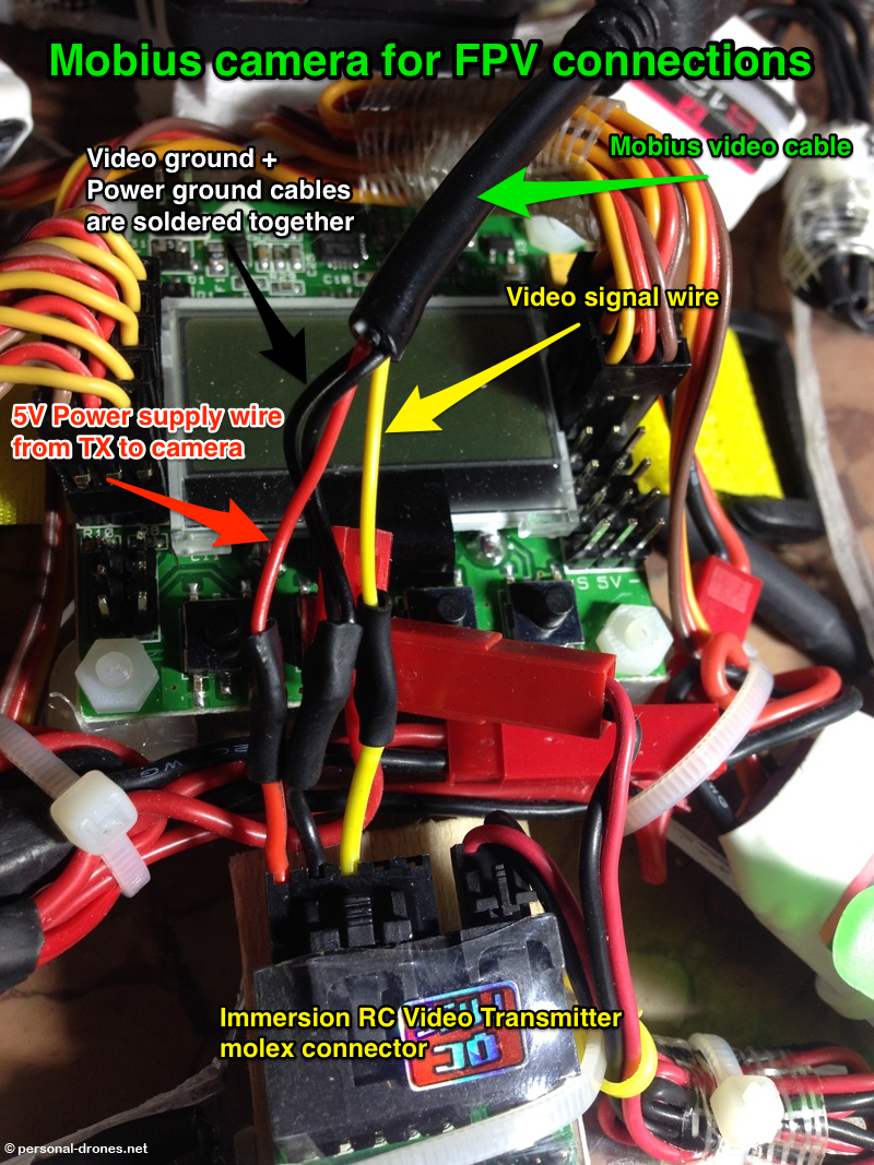
Here’s a picture in which the power wires were connected along the video signal wires. In this case the wires from the mobius video cable were soldered directly to the wires of the molex, with no connectors in between:
Another example of setup for the mobius camera for FPV in which the wires were soldered directly and the power wires were connected in addition to the video wires
Here’s another pilot that brings a bad reputation to quadcopters and personal drones. This guy thought he could land his DJI Phantom from his little balcony and very fly over Manhattan NYC at high altitude, what a great idea. Amazing and unique footage, however it’s just for chance that nobody got seriously injured. The FAA says it does not allow the flight of UAV over densely populated areas.
Interesting to note that the phantom looks very resistant to the impact on buildings, seems to hit several times and still fly afterwords. Also, it looks like the pilot is somehow controlling the flight, however he was not wearing goggles, so was this a line of sight flight?
The story:
Here’s the full video, however it looks like the crash moment is missing.
Horrible multirotor crash in the middle of the crowd. It seems like the drone first gets short of power (end of the battery?) and then goes entirely out of control, maybe for a late (too late) attempt to get it out of the area. Some people should know better, this gives a bad reputation to our hobby
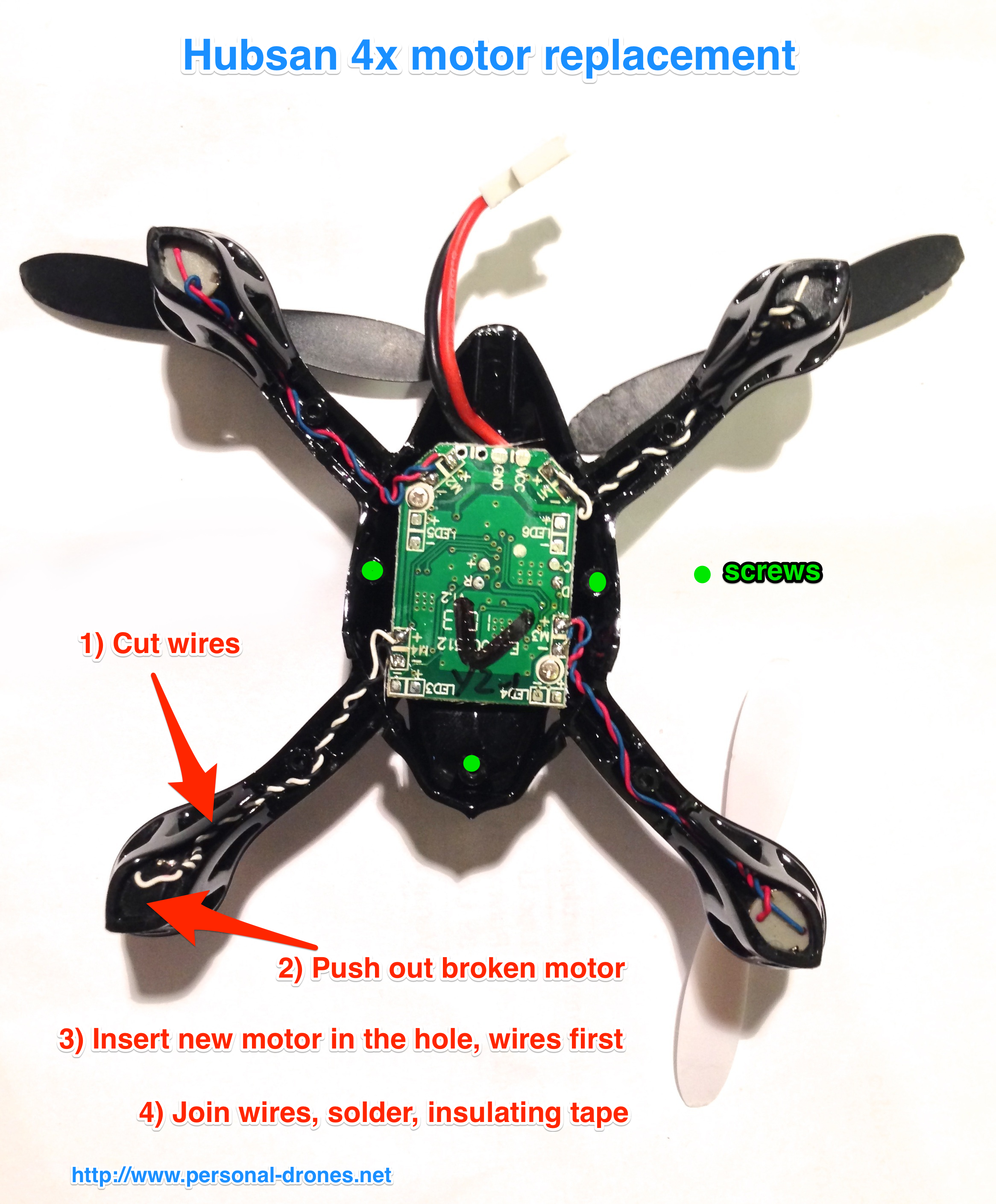
The Hubsan 4x is an extremely fun microquadcopter to fly. Sometimes, maybe after a crash, a motor stops working and replacement is required.
Unfortunately motors wires are soldered directly on the controller board. No connectors. The spare motors that can be bought online indeed come with 2 “naked” wires.
I had to replace a motor on an Hubsan 4x for a fiend today. What I did was to open the Hubsan 4x, it is hold together by 3 tiny screws and 4 little plastic pins located halfway on each of the arms. So once the screws are removed, you still have to play a bit, gently, to take apart the two halves.
Once the quadcopter is open, first step is to cut the wires of the faulty motor, approximately 1cm from the the body of the motor, so as to leave a generous length of the wires soldered to the board.
The motor can be extracted by pushing it from below with a screwdriver or a pen. The new motor can be now inserted, but first the wires of the new motor have to go through the motor hole.
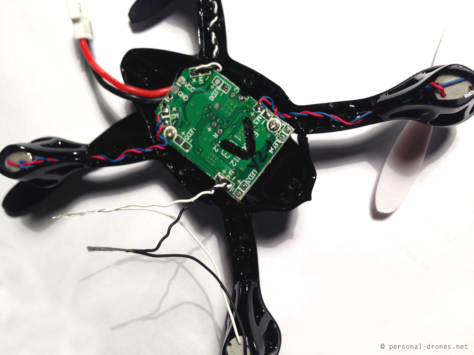
Then, you uncover the final 0,5cm of each of the 4 wires, the two of the original motor, soldered to the board, and the two from the new motor and join them together as in the picture below:
Replacing an Hubsan 4x motor involves some soldering, but not to the controller board!
Then the two junctions can be soldered easily. Some insulating tape on each of the junctions will finish the job. Here’s an excellent video about the basics of soldering, highly recommended:
http://www.youtube.com/watch?v=BxeDkcAa4Fs
####
This post is sponsored by Apps4Rent
Monitor, edit configure files and go mobile like the quadcopters by carrying your virtual PC on the cloud and access it via your mobile device using CloudDesktopOnline.com, Powered by one of the best Daas provider – Apps4Rent.
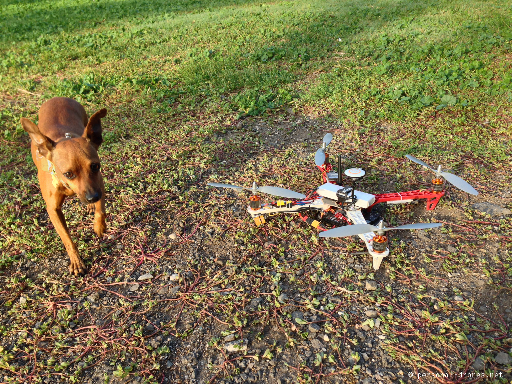
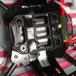
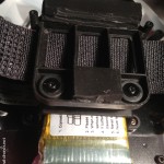
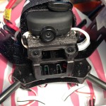
Finally finished the setup of the DJI Flamewheel F450 and went out for a first flight test very early in the morning at the park, with the idea to avoid kids.
Love kids but I feel that at this stage (of my flying skills), it could be dangerous for them, as they tend to come close to see the strange flying thing and are totally unaware of the possible dangers, those rotating propellers are like blades.
I discovered that dogs, that are indeed at the park early in the morning, are as curious as kids:
Just like kids, dogs are VERY curious about drones
Anyway it was my very first flight with a NAZA quadcopter, and it took a few tries to take off because of my poor acquaintance with the settings and led light codes. The quadcopter needs GPS calibration, entirely forgot about that. Then, in atti and atti GPS modes, the throttle becomes effective only after the midpoint, which was kind of misleading to me. At the end, all was good. Took a couple of short videos while the quad was locked in GPS mode, holds the position beautifully. Video is very short as I did not really trust the quad in this very first flight. Here you go:
This post is work in progress toward flying the thing, which still has to happen for a very stupid problem illustrated at the end of this post 🙂 Still, there is some information worth sharing. So here we go with the Hobbyking Integrated PCB Micro Quad PNP with kk2.0 flight controller assembly and setup (check out our tutorial on how to update the KK2 board firmware to the last version).
First impact is excellent, this little thing is quite different from the various walkera models of micro-quads as it looks like the big quadcopters, with clearly distinguishable motors, escs, flight controller, except that everything is very small. Could this model be a better personal drone than say, the ladybird or spacewalker models? It looks like the payload could be significantly higher, and maybe wind resistance could also be better thanks to the weight.
It does not look very strong though, and indeed I found some complaints posted around with reports of easy breaking frame parts after a crash. Will fly with care.
For the setup, I had looked at a couple of videos from hobbyking, in which the words “easy”, “quick setup”, “beginners” looked like the main keywords, and everything looked indeed quick and easy.
I am referring to these videos:
So, very confident that I would be flying by the evening, I started the quick and easy setup. Unpack everything. No manual included. But no worries as there is the “files” section on the product page on hobbyking.
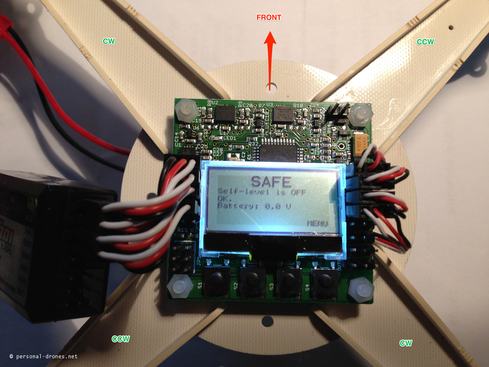
First thing that is not obvious, which is the front of the quad? The location of the power lead is not really helpful. Never lit a kk board before. I look at the manual available on the HobbyKing page:
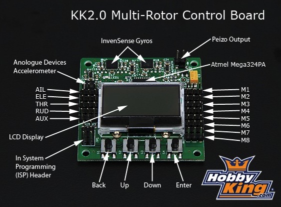
The picture of the quad with the board is not like the one I have and does not help with orientation. It’s easy, though, to find a picture of the board online:
and another one, extremely useful:
so now I know which is the front. Tough to be a beginner.
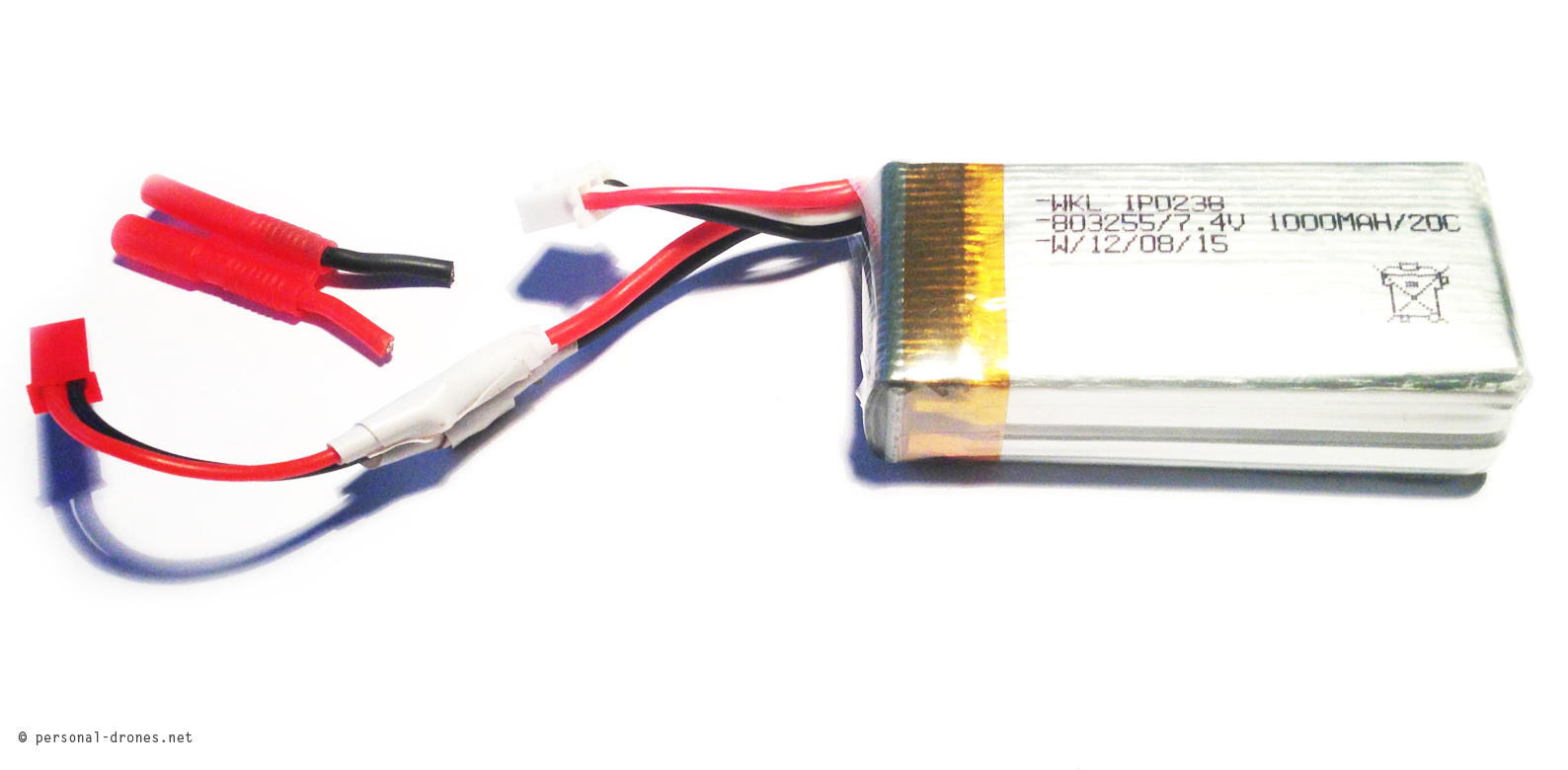
You could argue that I could have just lit the board to check out. However at this stage I was not willing to turn it up before I had read and understood some more, and more importantly I did not have a battery with the correct voltage (7,4V) and a JST connector.
This was solved by taking one of the 1000mAh 7,4V batteries for my Hoten-X, cutting the HTX connector out and soldering a spare JST connector I had around:
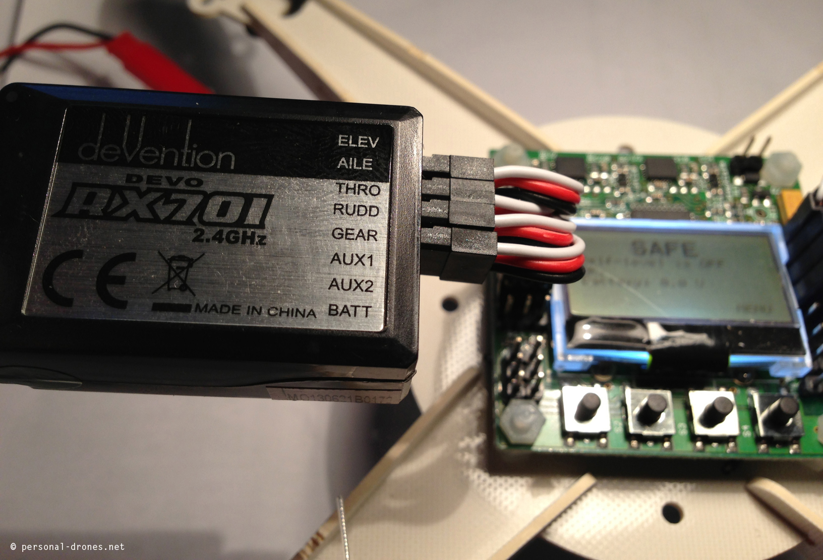
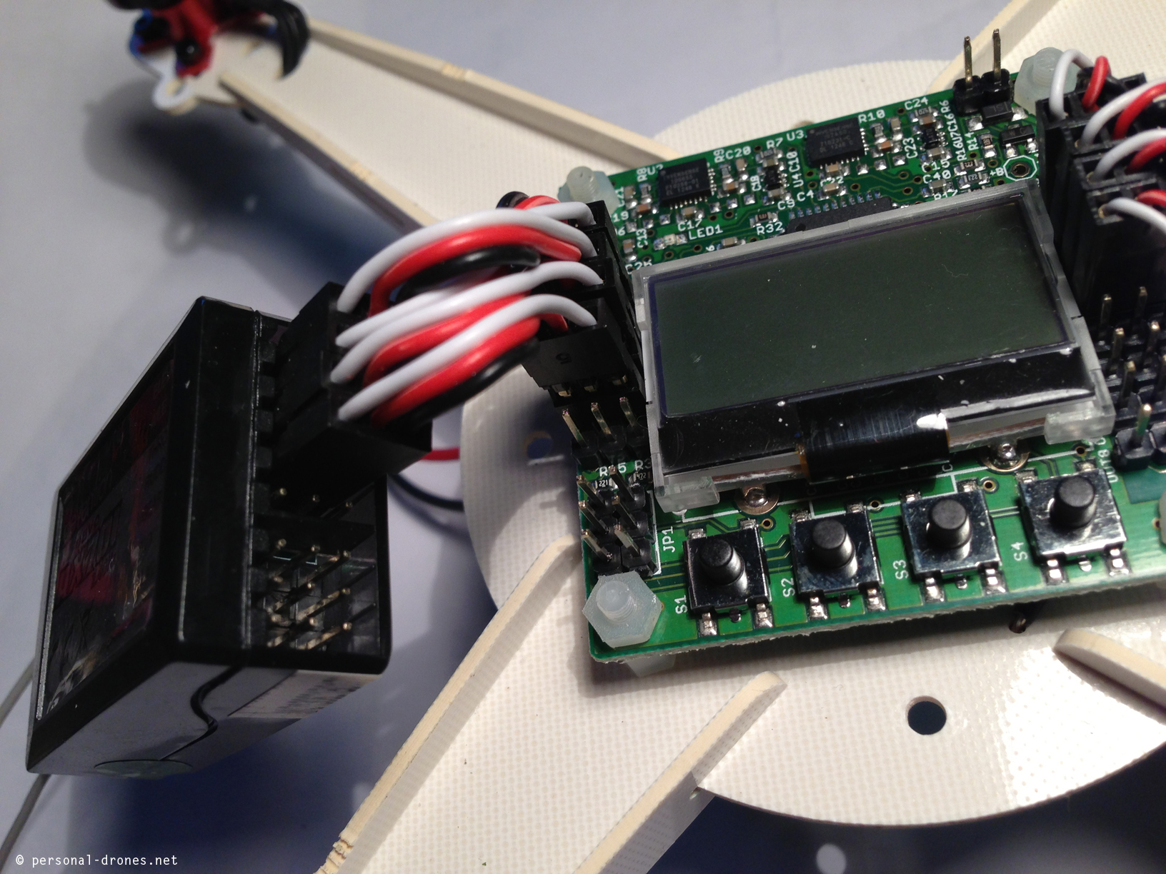
I can now power the quadcopter. However before doing so, I decide to hook up the receiver. First go is with a Walkera RX701 that I plan to use with my DEVO7 radio.
By looking at the board alone, there are at least two places where I could place the servos: to the right, where the ECSs servos are already hooked up, or the the left, where a number of servos pins are located. At this time, I still did not have seen the pictures of the KK2 board I posted above, and was really unsure. The pictures however solved this, the receiver has to be hooked to the left pins. The servo cables are to be inserted on the board with the black wire on the border side of the board. See also pictures below. To connect to the walkera RX701 the channels are almost in the correct order, except for a swap needed:
Walkera RX701:
– elev
– aile
– thro
– rudd
KK2 pins:
– aile
– elev
– thro
– rudd
so pin 1 corresponds to position 2 on the transmitter, and pin 2 to position 1.
Here’s how it looks like:
You can see in the picture that the last (lower) pin on the left of the board remains unused with this setup.
I was finding the manual quite useless as it refers to a previous version of the quad. For instance according to the manual, a procedure called ESC calibration should executed, that is extremely IMPORTANT (in red, big and bold in the manual).
First step is “turn yaw pot to zero”. What the heck is yaw pot, I have no clue. Turns out the board referred to in the manual, which is different from the one I have, has 3 potentiometers for yaw, pitch and roll that can be manipulated with a screwdriver. This does not apply to the kk2 board I have.
I decide to drop the manual and follow the simple checklist in a file, also linked in the product page, called Microquad quick guide with ESC cal, a simple textfile with a few (12) quick and easy steps to fly the thing. These are actually 13 steps as number 8 is repeated twice and refers both to esc calibration and mounting propellers, see below. Here are the file contents, it’s a short read:
Guide
connect the kk2.0 board to your receiver with the following connection
from the top
AIL - Ch1
ELE - CH2
THR - Ch3
Rud - Ch4
Aux - Ch5
Make sure the ground (black wire) is on the edge of the board
2. connect the battery and turn the board on (with your TX on
3. go into the menu and go into receiver test
4. move the sticks around on your tx and ensure that it is moving to the correct side, say if you move the rudder stick to the left and it says right, then reverse the it in your tx settings
5. after all the sides are correct, set the trim so that the kk2.0 board see all 0's
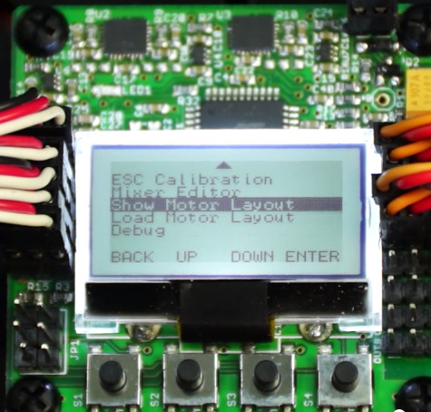
6. exit the receiver test and go into show motor layout
7. ensure that it shows a quad-x not anything else, if it shows something else go into the load motor layout settings and change it from there
8. Calibrate ESC.
a. Turn on transmitter and put throttle on max
b. Press both outer buttons on board while plugging in battery (at the same time!)
c. Hold both buttons pressed for over 10 seconds until your fingers really hurt. Several beeps and melodic ones. After the melodic ones, you can release.
d. Power cycle quad.
8. put the props on the quad, make sure you are using the correct props, on the right side, it will tell you on the layout which one spins which side
9. exit the menu until you see "safe"
10. leave the quad on the ground
11. move the throttle to 0 and all the way to the right to arm the quad
12. start flying
Looks very promising and it is indeed for the kk2 version with embedded screen which is the one I have.
So let’s get started. Hooking up of the receiver was OK, as described above.
2) Power the radio (created a new model on the DEVO7 for the mini quad before doing this) and then power the quad by attaching the battery. The display indeed lights up and show a “safe” label. This is to indicate that moving the transmitter sticks will not work at this stage, so the quad is “safe”, propellers will not spin. To “arm” the quad (the board will display “armed”), you have to move the throttle stick to the lower-right position, but we do not need to do this right now.
3-4-5) By navigating the menu, go to receiver test. This is easy, menus are navigated with the 4 black buttons at the bottom of the screen (it is NOT a touch screen as I thought for a few seconds!). The receiver test is the second item of the menu. It allows you to do two important things:
a- check if the direction of the sticks input is correct
b – set the subtrims correctly
for the first, you move the sticks up and down, left and right and see if the direction corresponds to what appears on the screen. You can check for example that when you move the right stick forward (in mode 2 this is for elevator, and allows to move the quad forward or backward), the screen says “forward” for elevator. I found out I had to actually reverse, on my DEVO7 transmitter, the aileron and elevator channels. This is done by going in the “FUNCTION” menu, and then in the REVSW submenu in the DEVO7.
Then you can set the subtrims on the radio in order to get all the trims displayed on the board to zero. The SUBTR menu is under the FUNCTION menu of the DEVO7, bringing the trims to zero (or very near) was actually a matter of some trial and error to get the direction of the corrections right, but no major issue with this one.
All is starting to look very good and easy, now that I spent about 3 hours to work out the basics reported above in this post 🙂
8) Calibrate the ESCs. This is where I failed miserably, or at least was unsure of the outcome with the DEVO7 and decided to switch to a Turnigy radio and receiver. The procedure requires to power the radio up with throttle to max. I was unable to do this at all, since if the DEVO7 is powered up with the throttle up it gives a THSTK error. If it is powered with the throttle down, and then the throttle is lifted up immediately afterwords, the DEVO immediately and prematurely emits the “second beep” it usually does at startup. After this second beep, on powering on the quad, binding to the receiver will not occur.
So I decide to do the procedure anyway, by putting full throttle only after binding has occurred. This seems to work, I can power up the radio, power up the quad with the two outer buttons pressed (will show “calibrating escs” message) and then put full trottle up immediately after binding. I do this but I am far to be convinced from the output. There is a lot of beeping going on, little beeps music, I have no clue about what is going on, when I should stop, if and when I should lower the throttle stick and release the buttons. Big mess. I would really appreciate if there was an official hobbyking video on youtube showing the procedure. If the video is there, I did not find it.
If you know about a good video for esc calibration on the kk2 board thanks for posting a comment to this post. I indeed found several videos around, with subtle or even gross variations on the procedure and at this time I am still unsure if I did the procedure correctly or not. Why? Keep reading.
** Update: I got some advice from Dennis Baldwin, see his vid below on configuration of the KK2.0 board, on this DEVO7/KK board/throttle up esc calibration issue. Here are 2 tips he posted on youtube on reply to my question on this topic. Will try them out at my next go with this setup.
Tip 1: “….Have you experimented with using a fixed ID for binding? I know the WK-2801 supports it and from what I understand binding happens much quicker, which may allow you to get around this problem.”
Tip 2 “and another tip I read from RC Groups: “if i remember correct once the devo is binded to the rx you can unplug the battery to the rx and it remembers the ID …so try this…turn on the tx , plug in the battery to the rx and let them bind…then unplug the battery and place the throttle to high position then plug the battery back in and the tx/rx should rebind quickly and allow you to do the calibration…”” **
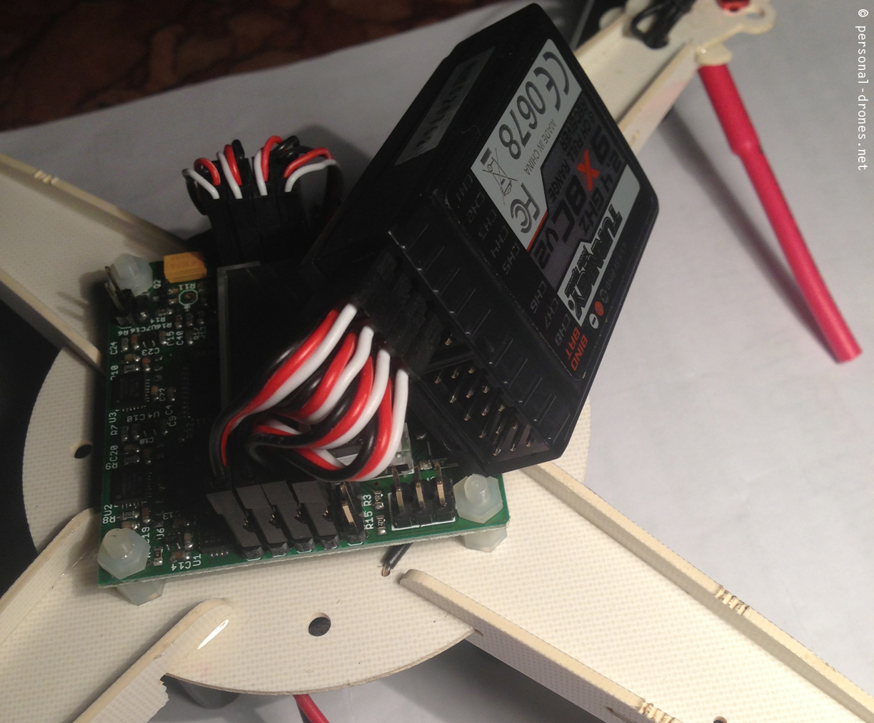
Given the problems with the throttle stick reported above, I decide to try with another radio and receiver I recently got from HobbyKing, the interesting Turnigy 9x V2 system.
It is the evolution of a first model that had several software issues that supposedly were fixed in this V2 version (well, actually already found a couple of evident bugs on this one, but it looks plenty usable for now). It looks like a complete, full featured 9 channels 2,4GHz radio system with receiver included for less than 55$. Amazing.
So I start over with hooking the turnigy receiver that came with the radio, 9X8CV2.
There is now a perfect correspondence of the channel order.
I go through the radio monitor menu to check sticks direction, and find that I have to reverse the elevator and rudder channels this time. Setting the rudder subtrim to zero seems diffcult, seems to want to remain at -3 for some reason, however this does not look like a big deal.
I can now power on the radio with full throttle on with no errors or issues at all.
Back to ECS calibration. I found a short video detailing the procedure, very convincing. The procedure illustrated in this video is extremely short and very different from the procedure explained in the text file I posted above. What I did was to follow a slightly modified procedure, very similar to the video. In the video, I would guess because it’s difficult to hold down the two lateral buttons of the board and AT THE SAME TIME plug the battery in, the battery is plugged into the quad with the first servo disconnected. When the servo is connected the board powers up.
This is the video from subaru4WD. I had a couple of comments from the author that are worth reporting here:
– this video was recorded with a kk board with firmware version 1.2, while the current version is 1.6.
– ESC calibration method is still the same though.
– With some ESCs, the method of starting with m1 unplugged and plugging it afterwards would actually cause the ESC’s to spin full throttle instead of entering calibration mode, which could be very bad if the props were left on.
This is really precious information Subaru4WD, thank you! And here’s the video.
For the record, here’s another excellent video from Dennis Baldwin that details several aspects of the configuration on the KK2 controller board including auto level
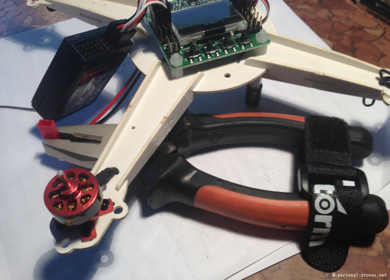
In order to overcome the problem of inserting the battery while the buttons are pressed, difficult to do with just two hand (if you have 3 then no problems for you), I locked the power connector of the quad in a plier, to keep it firmly in place. This does the job of the third hand and now it’s easy do to the required move:
As you can see, in this video there are 2 steps. You first start the radio with throttle up, then power the quad with the two lateral black buttons pressed. Once you hear 2 beeps, you put the throttle to zero on the radio and wait for one more beep. Then release black buttons. This is DIFFERENT from the instructions in the text file.
To summarize the ESCs calibration method I used:
– lock power connector with pliers, as in the photo above
– power radio with throttle up
– press the two lateral black buttons of the kk2 with one hand, and plug the battery plug with the other hand
– after the escs bip twice, throttle stick down
– you will hear again 2 beeps (that’s slightly different from what happens in Subaru’s vid), and then a single bip
– release buttons.
Will the quad now fly correctly? Well I don’t know. Why? Here’s why:
When I was about to mount the last propeller, I realized I was sent 1CW propeller and 3CCW. Contacted HobbyKing about this issue and ordered some spare propellers (will need them anyway).
**update: HobbyKing credited me 3$ for the error in the propeller. 3$ is the price of a full set of 6 propellers. They say they took steps to avoid this kind of problem happening again in the future, so I am happy with HobbyKing service at this time 🙂 **
So this is where I stand now, unable to do the flying tests and possibly the maiden flight until I get some new mail from HobbyKing. Stay tuned for developments.
If you have any comments on this post or want to share your thoughts or experience with the setup of the Hobbyking’s Integrated PCB Micro Quad PNP with kk2.0 flight controller I’d really love to hear!
The following two short clips were shot in Villa Borghese in Rome with the Walkera brushed Hoten-X quadcopter with wide angle 808 camera #16 setup illustrated in the previous post. Video was stabilized with Final Cut.
The light was just perfect at around 8 in the morning, shortly after sunrise. Wind was very gentle.
So unless I improve my pilot skills, which is actually happening every day, this is about the best I can get now with this equipment. It’s starting to be decent although still far from the nice footage I am aiming at.
Stay tuned for developments!
An aerial view of the Globe Theatre in Rome, Villa Borghese
An aerial view of the Pincio in Rome, Villa Borghese
So far we have been experimenting a bit with the most small devices, Hubsan H107C and Walkera Ladybird or Spacewalker with a normal 808 camera onboard. The video we could capture with those, is basically poor. This is because the quadricopters are very small, lightweight and wind sensitive. This makes the video inherently shaky. The relatively low quality of the cameras does not really help to get a great result.
Those are still valid devices maybe in situations in which a bigger drone would attract unwanted attention, and the event to be captured is still worth the poor quality, maybe because it is interesting for other reasons anyway, as it happens for so many videos we see on youtube.
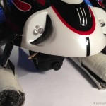
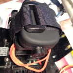
Anyway, as a next step I took of the DEVO-4 FPV camera off my brushed Hoten-X quadcopter and I built a little sorbothane basis to attach a 808 #16 camera with a velcro strap. Since the lens of the camera was nearly to the floor after mount, some foam was added to skids to gain some free space under the camera. See the picture gallery.
A step to attach a sorbothane base for 808 camera to the Walkera Hoten-X
Sorbothane base for 808 camera on Walkera Hoten-X, finished. Note the velcro ready to secure the camera
808 #16 camera strapped to Walkera Hoten-x
Walkera Hoten-X with onboard 808 #16 camera
808#16 camera on Walkera Hoten-X Brushed
The resulting video is a net improvement over the previously captured footage. Stability is much better, no traces of Jello effect, possibly thanks to the sorbothane mount and the mount for the DEVO-4 with little rubber foots that I left in place.
I recently received a package from UK with a BNF IFly4S. I connected it’s flight controller to a Walkera Devo RX701 2.4Ghz 7ch Receiver (Walkera-Parts-RX701) in order to be able to control it with my DEVO7 radio, best radio I have so far. Connection was not difficult although it took a while as it was my first connection between a receiver and a flight controller, ever.
The flight controller was then connected to a PC with Ifly Tools installed and calibration of the radio was done. Had a few problems on this one, but eventually succeeded also thanks to a couple of youtube videos that you will find in the specific models section.
Then comes the first flight test. Will it work? Please find out in the video below.
A quest toward the perfect quadcopter or multirotor for aerial video and personal flying freedom and a permanent survey on the latest quadcopter news and multirotor news
This website uses cookies to improve your experience. We'll assume you're ok with this, but you can opt-out if you wish.AcceptPrivacy and Cookies Policy
Privacy & Cookies Policy
Privacy Overview
This website uses cookies to improve your experience while you navigate through the website. Out of these, the cookies that are categorized as necessary are stored on your browser as they are essential for the working of basic functionalities of the website. We also use third-party cookies that help us analyze and understand how you use this website. These cookies will be stored in your browser only with your consent. You also have the option to opt-out of these cookies. But opting out of some of these cookies may affect your browsing experience.
Necessary cookies are absolutely essential for the website to function properly. This category only includes cookies that ensures basic functionalities and security features of the website. These cookies do not store any personal information.
Any cookies that may not be particularly necessary for the website to function and is used specifically to collect user personal data via analytics, ads, other embedded contents are termed as non-necessary cookies. It is mandatory to procure user consent prior to running these cookies on your website.